1. Project Background
The project began with a request from SMK Bina Kerja Purwakarta, West Java, Indonesia, for a 3-axis CNC machine intended for education and practical training. The objective was to provide students with a machine that could be used to learn CNC operation, CAD/CAM workflows, machining fundamentals, coordinate systems, tool setting, G-code execution, and basic manufacturing practices. The required machining volume was 700 × 400 × 350 mm for the X, Y and Z axes respectively. The machine was specified with a manual tool-change system and Mach3 as the CNC controller.
2. Stage 1 – Customer Requirement and Engineering Planning
Requirement Definition. The first stage is to translate the school’s educational needs into engineering requirements. The team reviews the required work envelope, expected materials, machine usage, operator safety, available electrical power, workspace, and learning objectives. The 700 × 400 × 350 mm machining volume becomes the main reference for sizing the machine structure and axis travel.
System Concept. A 3-axis architecture is selected, consisting of X, Y and Z linear motion. The spindle moves relative to the workpiece according to the selected machine configuration, while Mach3 provides the motion-control interface. Manual tool change is selected so students can learn tool identification, tool installation, tool length setting and safe setup procedures.
3. Stage 2 – Mechanical Design and CAD
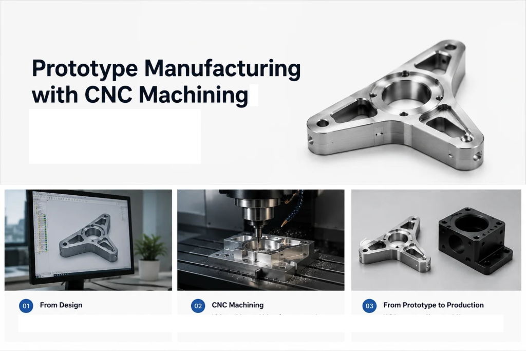
The engineering team develops the machine concept in 3D CAD. The design includes the base, frame, gantry, work table, X/Y/Z axis assemblies, spindle mount, linear guides, ball screws, motor mounts, electrical cabinet and operator interface. The CAD model is used to verify component locations, clearances and accessibility before fabrication begins. The design must provide sufficient rigidity so that cutting forces do not produce excessive deflection. At the same time, the structure must allow the required 700 × 400 × 350 mm machining volume.
Design verification. Engineering drawings are prepared for fabrication, including dimensions, hole patterns, mounting interfaces, material requirements and assembly references. Critical interfaces are checked so that the linear guides, ball screws, motors and spindle can be aligned accurately during assembly.
4. Stage 3 – Material Selection and Preparation
After the design is released for manufacturing, raw materials are prepared. Structural steel is commonly used for the machine frame because it provides strength and rigidity, while selected aluminum or machined steel components may be used for brackets, plates and mounting parts. Materials are inspected, measured and cut according to the engineering drawings. Correct material preparation is important because dimensional errors introduced at this stage can make later assembly and alignment more difficult.
5. Stage 4 – Frame Fabrication
12. Final inspection, delivery and operator orientation
The machine frame is fabricated through cutting, drilling, fitting and welding operations. The base and supporting structure are assembled carefully to maintain squareness and rigidity. Welding is performed in a controlled sequence to reduce distortion. After welding, critical surfaces may be ground, machined or corrected so that the linear-guide mounting surfaces can be installed accurately. The frame is then inspected for dimensions, level, squareness and overall structural integrity.
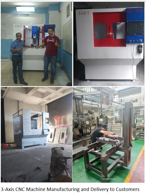
Project photographs: CNC machine fabrication, assembly and completed machine.
6. Stage 5 – Precision Machining of Components
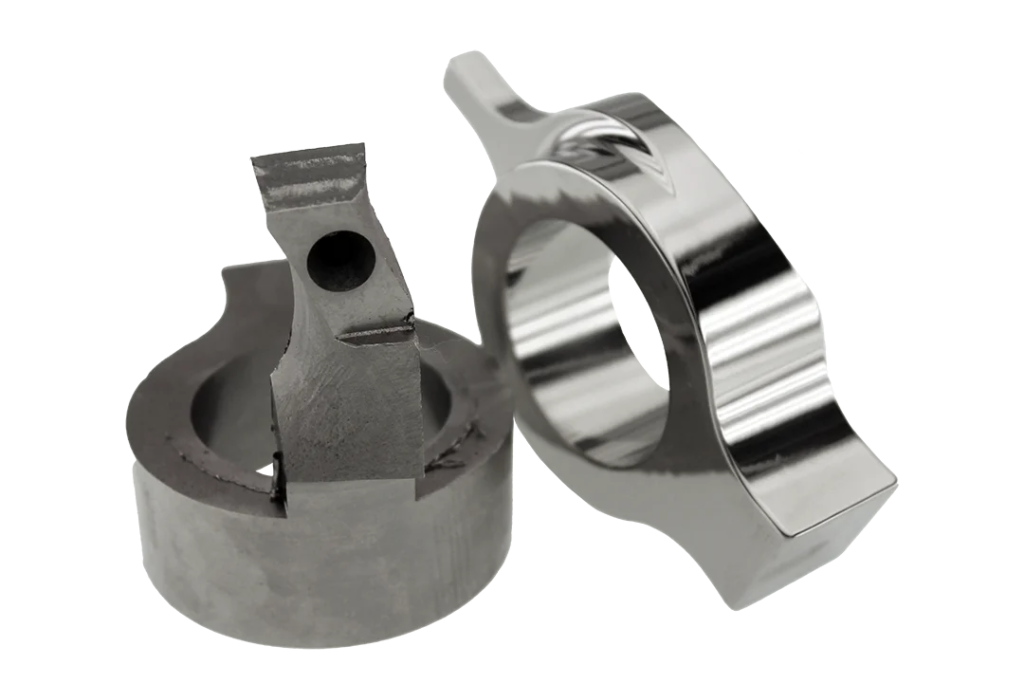
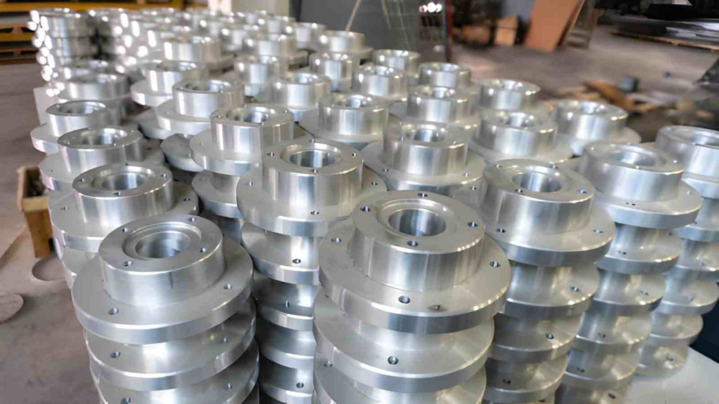
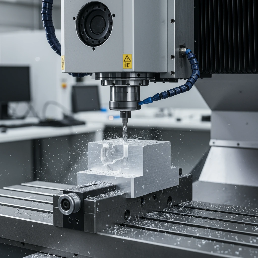
Key components are manufactured or finished using precision machining processes. Typical parts include motor mounts, bearing supports, spindle plates, brackets, table components and other interfaces that require accurate dimensions. Machining is performed to achieve the required fit and alignment. The linear guides and ball screws are especially important because they determine the smoothness and repeatability of X, Y and Z movement.
Axis system. The X axis provides longitudinal movement, the Y axis provides transverse movement, and the Z axis provides vertical movement. Each axis must be mechanically capable of reaching the intended working range while maintaining stable motion under machining loads.
7. Stage 6 – Mechanical Assembly and Alignment
The fabricated frame and precision components are assembled into the complete mechanical system. Linear guide rails are installed and aligned, followed by the ball screws, bearing blocks, axis carriages and drive motors. The spindle assembly is mounted to the Z-axis structure. Each axis is checked for smooth travel, backlash, binding and parallelism. Mechanical alignment is essential because even a small angular or positional error can affect machining accuracy.
Manual tool-change arrangement. The spindle is configured for manual tool changes. During operation, the machine is stopped safely before the operator removes and installs a cutting tool. This arrangement is suitable for an educational environment because it exposes students to practical tool-setting procedures.
8. Stage 7 – Electrical System and Mach3 Controller
The electrical system is installed after the mechanical system is sufficiently complete. The control panel includes the power supply, motor drivers, protection devices, emergency-stop circuit, switches and wiring required for the CNC system. Stepper or servo motors are connected to the corresponding axis drives. Limit or home switches can be used to establish machine references and improve operational safety.
Mach3 configuration. Mach3 is configured as the machine controller. The X, Y and Z axes are assigned to their respective motor outputs, and parameters such as steps per unit, direction, velocity and acceleration are set according to the machine’s mechanical characteristics. The control interface allows the operator to load and run G-code programs and monitor axis coordinates.
9. Stage 8 – Software Setup, Testing and Calibration
Before production use, the CNC machine undergoes systematic testing. Each axis is jogged through its available travel to verify direction, smoothness and limit operation. The Mach3 coordinate display is checked against actual machine movement. Steps-per-unit calibration is performed so that commanded movement corresponds as closely as possible to actual travel. The spindle and emergency-stop functions are also checked.
Test machining. A sample program is executed on a suitable workpiece to verify coordinated X, Y and Z motion. The resulting part is inspected for dimensional accuracy, surface condition and overall machining behavior. If necessary, mechanical alignment, drive parameters or Mach3 settings are adjusted and the test is repeated.
10. Stage 9 – Final Inspection, Delivery and Educational Handover
After successful testing, the machine is cleaned, inspected and prepared for delivery to SMK Bina Kerja Purwakarta. The final inspection covers mechanical condition, electrical safety, controller operation, axis movement, spindle operation and the manual tool-change procedure. The machine is then delivered and positioned at the customer’s facility. Operator guidance can include basic machine operation, machine zero/reference procedures, tool setting, workpiece setup, G-code loading, Mach3 operation and safe shutdown.
11. Final Result and Educational Value
The completed machine is a 3-axis CNC system designed around a 700 × 400 × 350 mm machining volume, manual tool change and Mach3 control. The manufacturing process integrates mechanical engineering, precision fabrication, electrical control, CNC programming and machine calibration. In an educational environment, the machine can support practical learning in CNC operation, machining, CAD/CAM, coordinate systems, tooling, measurement and problem solving.
The project demonstrates a complete engineering workflow: understanding customer requirements, converting requirements into a CAD-based design, preparing materials, fabricating and machining components, assembling the mechanical and electrical systems, configuring Mach3, testing and calibrating the machine, and finally delivering a functional CNC platform for student training. The result is not only a machine, but also a practical learning platform for developing manufacturing skills.
12. Summary of the Manufacturing Sequence
1. Customer requirements and technical planning
2. Mechanical concept and 3D CAD design
3. Engineering drawings and design verification
4. Material selection, cutting and preparation
5. Frame fabrication, welding and dimensional correction
6. Precision machining of critical components
7. Installation and alignment of X, Y and Z axis systems
8. Spindle and manual tool-change installation
9. Electrical wiring, motor drives and control panel installation
10. Mach3 installation and axis parameter configuration
11. Testing, calibration and sample machining