3D printing tolerances decide whether a printed part fits, slides, or snaps into place. A desktop FDM printer typically holds about ±0.5 mm, a well-tuned resin (SLA) printer can hold a few hundredths of a millimetre on small features, and powder processes such as SLS and MJF sit around ±0.3 mm. This guide shows what those numbers mean for a real part, how much clearance to leave between mating parts, and how thin a wall can be.
What Tolerance Means in 3D Printing
A tolerance is the amount a real dimension is allowed to differ from the dimension in your CAD model. If a 20 mm block is printed at 19.8 mm and the tolerance is ±0.5 mm, the part is in spec. If the tolerance is ±0.1 mm, it is not.
Three terms are often mixed up:
- Accuracy is how close a printed dimension comes to the CAD value.
- Precision (repeatability) is how close several prints of the same part come to each other.
- Tolerance is the band you decide is acceptable for the part to work.
A printer’s layer height or XY resolution is not its accuracy. A printer that lays 0.1 mm layers can still print a part that is 0.4 mm oversize, because shrinkage, warping, and nozzle squash all add error on top of resolution.
3D Printing Tolerances by Process
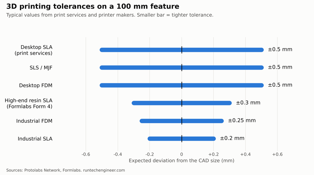
Most print services quote tolerance as a percentage of the dimension with a lower limit. The percentage applies to large features; the lower limit applies to small ones. Whichever is larger is the tolerance you can expect.
| Process | Typical tolerance | On a 20 mm feature | On a 100 mm feature | On a 200 mm feature |
|---|---|---|---|---|
| Desktop FDM | ±0.5%, lower limit ±0.5 mm | ±0.5 mm | ±0.5 mm | ±1.0 mm |
| Industrial FDM | ±0.25%, lower limit ±0.25 mm | ±0.25 mm | ±0.25 mm | ±0.5 mm |
| Desktop SLA (print services) | ±0.5%, lower limit ±0.15 mm | ±0.15 mm | ±0.5 mm | ±1.0 mm |
| Industrial SLA | ±0.2%, lower limit ±0.127 mm | ±0.13 mm | ±0.2 mm | ±0.4 mm |
| SLS and MJF (nylon) | ±0.5% or ±0.3 mm, whichever is larger | ±0.3 mm | ±0.5 mm | ±1.0 mm |
These are general figures from print services and printer makers, not guarantees for any one machine. A tuned desktop printer can beat them; a worn or badly calibrated one will not reach them.
The best resin printers now do much better than the service averages on small parts. Formlabs reports these typical tolerances for its Form 4 printers:
| Feature size | Typical tolerance (Form 4) | Example |
|---|---|---|
| 1–30 mm | ±0.15%, lower limit ±0.02 mm | 20 mm feature: ±0.03 mm |
| 31–80 mm | ±0.2%, lower limit ±0.06 mm | 50 mm feature: ±0.1 mm |
| 81–150 mm | ±0.3%, lower limit ±0.15 mm | 100 mm feature: ±0.3 mm |
The pattern is the same across every process: error grows with part size, so a long part needs a looser tolerance than a short one.
Which process for which tolerance?
- Around ±0.5 mm is fine (brackets, covers, jigs, fixtures): desktop FDM, the cheapest option. See FDM vs SLA for the trade-offs.
- Around ±0.1 to ±0.2 mm on small parts (snap fits, housings with screw bosses, fit-check prototypes): resin SLA, or industrial FDM.
- Strong, complex nylon parts with moderate tolerance: SLS or MJF. No supports are needed, so internal channels and moving assemblies are easier.
- Tighter than about ±0.05 mm: print the part slightly oversize and machine the critical features afterwards. Machining remains the way to hold fine tolerances; see our precision tolerancing service.
Clearance for Mating Parts
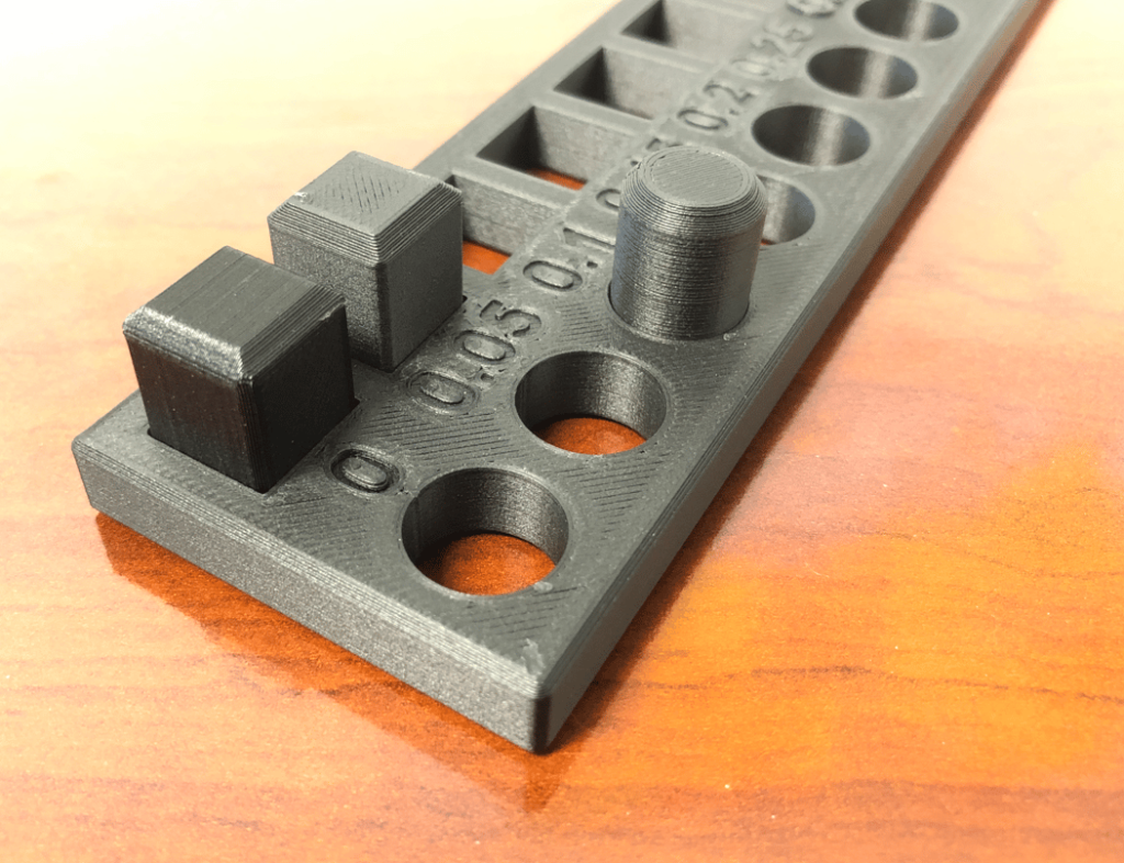
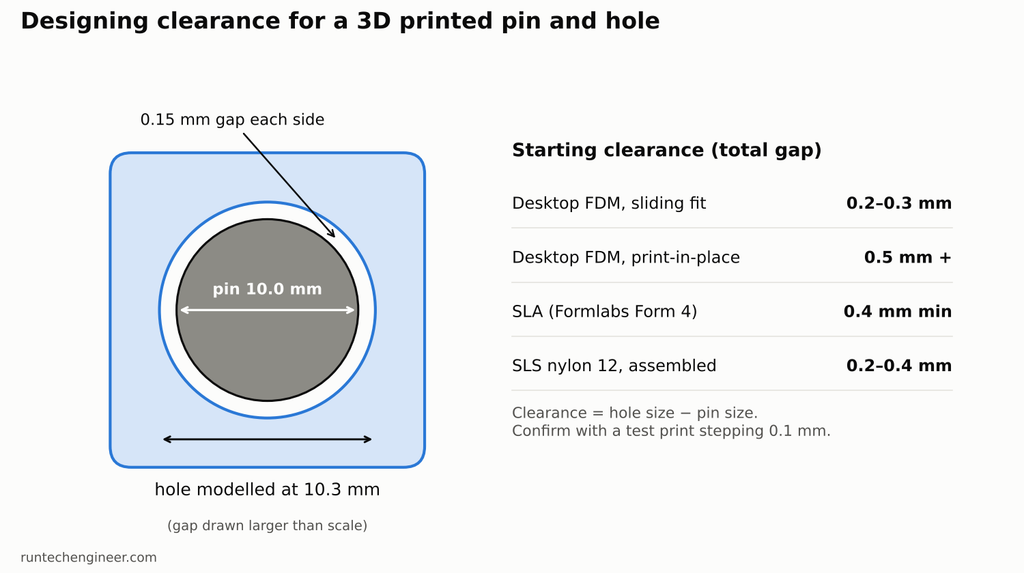
Clearance is the gap you design between two parts that fit together, such as a shaft in a hole, a lid on a box, or the moving pieces of a hinge printed in one go. Too little and the parts will not assemble or will fuse during printing. Too much and they rattle.
Start from these values, then adjust with a test print:
| Process | Parts printed separately, then assembled | Parts printed together (print-in-place) |
|---|---|---|
| Desktop FDM | 0.2–0.3 mm for a sliding fit | 0.5 mm or more |
| SLA (Formlabs Form 4) | 0.4 mm minimum | 0.4 mm minimum; below this parts may fuse |
| SLS (nylon 12, Formlabs Fuse) | 0.2 mm on small features, 0.4 mm on large ones | 0.3 mm on small features, 0.6 mm on large ones |
| SLS in flexible or nylon 11 powders | at least 1 mm | at least 1 mm |
In the Formlabs SLS guide, “small” means a mating feature under 20 mm² in cross-section and “large” means over 20 mm².
The clearance is the total gap, not the gap per side. For a 10 mm pin in a printed hole with 0.3 mm clearance, model the hole at 10.3 mm.
Holes and pins
Holes are where 3D printing tolerances cause most trouble.
- FDM prints vertical holes undersize. The nozzle squashes each line of plastic as it lays it down, which pushes the edge of the hole inward. The smaller the hole, the larger the effect.
- Horizontal holes print slightly oval in FDM and SLS, because the top of the hole is built as an overhang.
- For a hole that must be exact, model it slightly undersize and drill or ream it to size after printing. This is more reliable than chasing the last tenth of a millimetre in the slicer.
- Minimum hole size is about 0.5 mm in SLA and 1 mm in SLS before holes start to close up. Industrial FDM services set the minimum at about 1.6 mm.
- Small FDM pins are weak. Pins under about 5 mm in diameter are printed as perimeter only, with little bond to the part. Add a fillet at the base, or print a hole and press in a steel dowel pin.
For threads, an M3 or M4 thread printed directly into plastic seldom holds up. Heat-set brass inserts or captive nuts give a far stronger joint.
Minimum Wall Thickness for 3D Printing
Wall thickness is the thickness of any thin section of a part: a shell, a rib, a tab. A supported wall is joined to other walls on two or more sides. An unsupported wall is joined on fewer than two sides, such as a free-standing fin, and needs to be thicker.
| Process | Supported wall (minimum) | Unsupported wall (minimum) | Notes |
|---|---|---|---|
| Desktop FDM | 0.75–0.8 mm | 1.0 mm | Rule of thumb: at least 2 to 3 nozzle widths, so 0.8–1.2 mm with a 0.4 mm nozzle |
| SLA (Formlabs Form 4) | 0.2 mm | 0.2 mm | Thin walls can warp in washing; most print services ask for about 1 mm |
| SLS (nylon 12) | 0.6 mm vertical, 0.3 mm horizontal | 0.6 mm vertical, 0.3 mm horizontal | Many services treat anything under 1 mm as at the customer’s risk |
| MJF (nylon 12) | about 0.7 mm | about 0.7 mm | Same caution as SLS below 1 mm |
These are the thinnest walls the process can form. They are not walls that will carry a load. A 0.8 mm FDM wall prints fine but breaks easily, especially across its layers. For a part that takes real force, design the wall several times thicker and check it against the load. Our guides to PLA strength and PLA vs ABS vs PETG give the material numbers, and functional 3D printed parts covers how wall count and infill change strength.
In FDM, also match wall thickness to the nozzle. A 1.0 mm wall with a 0.4 mm nozzle leaves a 0.2 mm sliver that the slicer may skip or fill badly. A 0.8 mm or 1.2 mm wall prints as two or three clean lines.
How to Get Tighter Tolerances from a 3D Printer
- Calibrate first. On FDM, check steps per mm and extrusion flow, and print a calibration cube. Most fit problems on desktop printers come from over-extrusion, which makes every outside dimension too big and every hole too small.
- Print a fit test before the real part. Print a short coupon with the same hole or slot at several clearances, stepping by 0.1 mm, in the same orientation as the final part. Then use the clearance that works.
- Orient the critical features. In SLS and SLA, holes and pins are most accurate with their axis vertical. In FDM, vertical holes are round but undersize, while horizontal holes need support and come out oval.
- Chamfer the bottom edges. The first FDM layer spreads out into an “elephant’s foot” that makes the base oversize. A 45° chamfer or small radius on edges touching the bed hides it and makes the part easier to remove.
- Choose a stable material. ABS shrinks and warps more than PLA or PETG as it cools. See the material selection guide for the trade-offs.
- Allow for post-processing. Resin parts shrink slightly during post-curing, and sanding or bead blasting removes material. Leave stock on surfaces you will finish.
- Machine what must be exact. Print bearing bores and locating holes undersize, then drill or ream them. Use inserts and dowel pins where position matters.
- Only tolerance what matters. Put tight tolerances on the few surfaces that mate and leave the rest open. A clear technical drawing that marks the critical dimensions saves cost on any process.
A design-for-3D-printing review catches most of these issues before the first print.
3D Printing Tolerances FAQ
What tolerance can a 3D printer hold?
A typical desktop FDM printer holds about ±0.5 mm, or ±0.5% on large parts. Industrial FDM holds about ±0.25 mm. Resin SLA printers range from about ±0.15 mm on desktop machines down to a few hundredths of a millimetre on small features with the best current printers. SLS and MJF hold about ±0.3 mm.
How much clearance should I leave for 3D printed parts?
For desktop FDM, start with 0.2–0.3 mm for parts that slide together and 0.5 mm or more for parts printed already assembled. For SLA, leave at least 0.4 mm. For nylon SLS, 0.2–0.4 mm for parts assembled after printing. Confirm with a test print.
What is the minimum wall thickness for 3D printing?
About 0.8 mm for supported walls and 1 mm for free-standing walls in desktop FDM, 0.2 mm in a high-end resin printer, and 0.6–0.7 mm in SLS or MJF. Walls that carry a load need to be much thicker than these minimums.
Why are my 3D printed holes too small?
In FDM, the nozzle squashes each line of plastic as it prints, which pushes the edge of a vertical hole inward. Over-extrusion makes it worse. Calibrate flow, use the slicer’s hole compensation, or model the hole slightly undersize and drill it to size.
Is 3D printing as accurate as CNC machining?
Not usually. Standard CNC machining holds about ±0.13 mm (±0.005 in) on most features and can go much tighter. The best resin printers can match that on small parts, but FDM and powder processes cannot. Many production parts are printed close to shape and finished by machining.
Need Printed Parts That Actually Fit?
RunTechEngineer designs and prints parts with the right clearances, wall thickness, and process for the job, and machines the features that need to be exact. Explore our 3D printing services or contact us with your part and the fits it needs.