
Why Mach3 Setup Matters
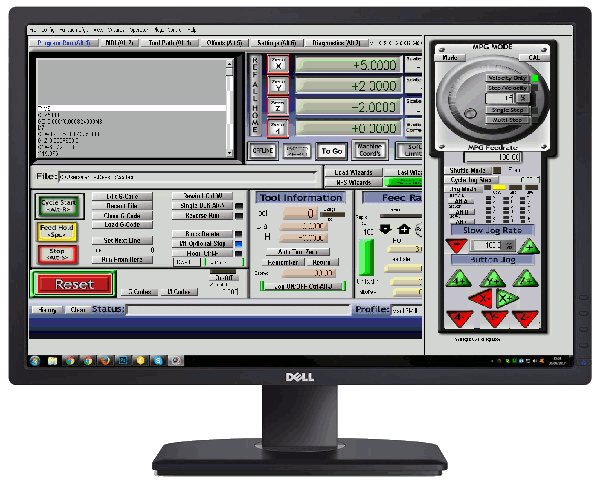
This Mach3 setup guide takes you from installation to a tested, working machine in six steps. Mach3 does not work out of the box for any specific machine. Every install has to be matched to the hardware it drives: the motors, drivers, limit switches, and spindle. Setup is the work of telling Mach3 which pin does what and how far each axis moves per pulse.
Getting that matching wrong is the most common source of frustrating, hard-to-diagnose problems later on. The steps follow the order that lets you test each part before building on it.
What You Need Before You Start
- A suitable PC. The parallel port driver only works on 32-bit Windows. A 64-bit PC or a laptop needs an external USB or Ethernet motion controller. If your control PC is too old to be reliable, see our notes on upgrading an older CNC controller.
- Your breakout board or motion controller manual. It lists which pin carries each step, direction, and input signal.
- The plugin for your motion controller, if you are not using the parallel port.
- Your Mach3 licence file. Without it Mach3 runs in demo mode, limited to 500 lines of G-code.
- A working emergency stop button, wired and within reach.
Keep the official Mach3 setup documentation open as a reference while you work.
Step 1: Install Mach3 and the Motion Control Driver or Plugin
A proper install is more than running the installer. Mach3 also needs the right way of talking to your hardware, and a mismatch here is the usual reason a machine fails to move at all on the first attempt.
- Run the Mach3 installer and accept the default folder,
C:\Mach3. - If you use the parallel port, keep the Parallel Port Driver option ticked, then restart Windows when the installer finishes. Run
DriverTest.exefrom the Mach3 folder afterwards to confirm the pulse timing is stable. - If you use a USB or Ethernet motion controller, untick the parallel port driver. Copy the controller’s plugin file (a
.dllfrom the manufacturer) intoC:\Mach3\PlugIns. - Copy your licence file into
C:\Mach3. - Start Mach3. When it asks which motion control device to use, select your plugin and tick “Don’t ask me this again”.
If you picked the wrong device, reset the choice from Function Cfg’s → Reset Device Sel and restart Mach3.
Step 2: Create a Profile for Your Machine
All settings are stored in a profile. Create your own instead of editing the stock one, so a reinstall or a mistake never costs you a working configuration.
- Open Mach3 Loader.
- Click Create Profile, clone from Mach3Mill, and give it your machine’s name.
- Start that profile, then set the units under Config → Select Native Units. Choose mm or inches now. Changing it later invalidates every motor setting.
Restart Mach3 after changing native units.
Step 3: Configure Ports and Pins
Config → Ports and Pins is where you tell Mach3 which pin drives each motor. Take the pin numbers from your breakout board manual.
- On the Port Setup and Axis Selection tab, enable Port #1. For a parallel port the address is usually
0x378. Leave kernel speed at 25,000 Hz to begin with. - On the Motor Outputs tab, tick Enabled for each axis you have.
- Enter the Step Pin# and Dir Pin# for each axis, and set Step Port and Dir Port to 1.
- Click Apply before leaving the tab.
Now test. Press Reset so it stops flashing, then jog each axis with the arrow keys and Page Up / Page Down.
- Axis moves the wrong way: toggle Dir LowActive for that axis.
- Axis does not move at all: recheck the pin numbers, then the driver’s enable signal.
Step 4: Set Steps per Unit, Velocity, and Acceleration
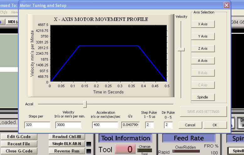
These three numbers make the machine move the right distance at a safe speed. Steps per unit means that commanding 10 mm of travel produces exactly 10 mm of real movement. Velocity and acceleration set how fast the axis can go without losing steps.
Open Config → Motor Tuning, select an axis, enter the values, and click Save Axis Settings before choosing the next axis.
The basic formula is:
Steps per unit = (motor steps per revolution × microsteps) ÷ travel per revolution
A 200-step motor at 8 microsteps on a 5 mm lead screw gives 320 steps per mm. Start with a low velocity and acceleration and raise them by testing. Our Mach3 motor tuning guide covers the full procedure, including how to verify the result by measuring.
These numbers directly affect part accuracy, which ties into the kind of precision tolerancing a shop can realistically promise.
Step 5: Set Up Limit Switches, Homing, and E-Stop
Limit switches and the emergency stop need to be configured and tested during setup, not left for later. A machine that can travel past its physical limits before Mach3 notices is a real safety and equipment risk.
E-stop first
- Open Config → Ports and Pins → Input Signals and find the EStop row.
- Tick Enabled and enter the port and pin from your board manual.
- Press the physical button. Reset should start flashing and refuse to clear until the button is released.
- If the behaviour is inverted, toggle Active Low for the EStop signal.
Limit and home switches
- On the same tab, enable the rows you have wired: X++, X–, and X Home, and the same for Y and Z.
- Enter the pin for each. Several switches can share one pin if they are wired in series.
- Open the Diagnostics screen (Alt-7) and press each switch by hand. Its indicator should light. If an indicator is lit while the switch is released, toggle Active Low.
Homing and soft limits
Open Config → Homing/Limits and set, for each axis:
| Setting | What it does |
|---|---|
| Home Neg | Tick it if the home switch is at the negative end of travel |
| Speed % | Homing speed as a percentage of the axis velocity. Start at 20 |
| Soft Max / Soft Min | The travel limits in machine coordinates |
| Slow Zone | Distance before a soft limit where the axis slows down |
| Auto Zero | Sets machine coordinates to zero once homed |
Then click Ref All Home on the main screen and watch each axis find its switch. Once homing works, turn on the Soft Limits button so Mach3 stops a move before it reaches a switch.
Step 6: Set Up the Spindle
Mach3 can control a spindle in two ways: by switching it on and off through a relay, or by controlling its speed through a PWM or step and direction signal sent to a VFD. Which one you use depends on your breakout board and spindle drive.
On/off control with a relay
- Open Config → Ports and Pins → Spindle Setup.
- Leave Disable Spindle Relays unticked.
- Assign the output numbers for M3 and M4.
Speed control through a VFD
- On the Spindle Setup tab, tick Use Spindle Motor Output and PWM Control.
- Set the PWM base frequency recommended for your breakout board.
- Go to the Motor Outputs tab, enable the Spindle row, and enter the step pin that carries the PWM signal.
- Open Config → Spindle Pulleys and enter the minimum and maximum speed of your spindle, so Mach3 can scale the signal correctly.
Test the spindle
From the MDI screen, run a command such as M3 S6000. Compare the actual speed with the commanded speed, then stop the spindle with M5.
If the two do not match, check the maximum speed in the pulley settings and the 0–10 V output of the breakout board before changing anything else.
Back Up Your Configuration
Once everything works, copy your profile file to a USB drive. It sits in C:\Mach3 and is named after your profile, for example MyRouter.xml. Restoring that one file brings back every setting in this guide.
Common Mach3 Setup Problems
Most first-time setup problems come from a small number of causes.
| Problem | Cause and fix |
|---|---|
| The motors do not move | Check that the correct motion control plugin is selected, that the port address or USB controller is detected, and that Mach3 is out of E-stop (Reset should not be flashing). On a 64-bit PC the parallel port driver will not work, so use an external motion controller |
| An axis moves in the wrong direction | Toggle Dir LowActive for that axis in Ports and Pins → Motor Outputs |
| The axis moves the wrong distance | Steps per unit is incorrect. Recalculate it, or use the axis calibration function on the Settings screen |
| The motors stall or lose steps | Velocity or acceleration is too high for the machine. Lower both and work upward again during motor tuning |
| Limit switches trigger for no reason | Usually electrical noise. Use shielded cable and increase the debounce interval in Config → General Config |
| Reset will not clear | The E-stop input is set to the wrong active state. Change Active Low for the EStop signal in Ports and Pins → Input Signals |
For problems that remain after these checks, see our guide to troubleshooting and calibration.
Need Help Setting Up Mach3 on Your Machine?
RunTechEngineer sets up Mach3 from the ground up, matching software settings to each machine’s hardware so it runs reliably from the very first job. See our Mach3 CNC controller services, including custom macros and screen sets, or contact us to get your setup started.
Pingback: Stepper vs Servo Motor for CNC Machines | RunTechEngineer
Pingback: Custom Mach3 Macros and Screen Sets
Pingback: Mach3 Troubleshooting and Calibration Services