Feeds and speeds are the two numbers that decide how a CNC cutter meets the material: how fast the spindle turns and how fast the tool moves through the part. Get them right and the tool cuts cleanly, lasts long, and finishes the job quickly. Get them wrong and the tool rubs, chatters, burns, or breaks. This guide gives the feeds and speeds formulas, explains chip load and chip thinning, lists starting values by material, and works through a full example.
What Feeds and Speeds Mean
- Speed is how fast the cutting edge moves past the material, called the surface speed or cutting speed. It is set by the material and the tool coating. The machine setting that controls it is the spindle speed in RPM.
- Feed is how fast the tool advances through the material, the feed rate, in mm/min or inches per minute. It is set from the chip load: the thickness of material each cutting edge removes per turn.
The two are linked. The surface speed fixes the RPM, and the RPM multiplied by the chip load and the number of flutes gives the feed rate.
The Feeds and Speeds Formulas
Spindle speed (RPM)
RPM = (1000 × Vc) ÷ (π × D) in metric units, where Vc is the surface speed in metres per minute and D is the tool diameter in millimetres.
RPM = (3.82 × SFM) ÷ D in imperial units, where SFM is the surface speed in surface feet per minute and D is the tool diameter in inches.
Both say the same thing: a smaller tool has to spin faster to give its edge the same speed through the material.
Feed rate
Feed rate = RPM × chip load × number of flutes
In metric, chip load (fz) is in millimetres per tooth and the feed rate comes out in mm/min. In imperial, chip load is in inches per tooth (IPT) and the feed rate comes out in inches per minute (IPM).
Chip load
Rearranging the feed rate formula gives the chip load your current settings produce:
Chip load = feed rate ÷ (RPM × number of flutes)
Chip load is the number that matters most for tool life. Too small and the edge rubs instead of cutting, which creates heat and dulls the tool fast. Too large and the edge chips or the tool snaps. Tool makers publish a recommended chip load for each tool size and material; treat it as the starting point.
Material removal rate
Material removal rate (cm³/min) = depth of cut (mm) × width of cut (mm) × feed rate (mm/min) ÷ 1000
This tells you how much material leaves the part per minute, which is the fairest way to compare two sets of cutting parameters.
Worked Example: A 6 mm End Mill in Aluminium
You are cutting 6061 aluminium with a 6 mm, 3-flute solid carbide end mill on a machine whose spindle reaches 24,000 RPM.
Step 1: pick a surface speed. Harvey Tool lists 500 to 1,000 SFM (about 150 to 300 m/min) for carbide in aluminium. Start in the lower half for a light machine: 200 m/min.
Step 2: calculate the RPM. RPM = (1000 × 200) ÷ (π × 6) = 10,610 RPM. That is within the spindle’s range.
Step 3: pick a chip load. Harvey Tool suggests about 0.002 inch per tooth for a 1/4 inch (6.35 mm) tool in aluminium, which is about 0.05 mm per tooth.
Step 4: calculate the feed rate. Feed = 10,610 × 0.05 × 3 = 1,592 mm/min.
Step 5: correct for a light radial cut. If you are cutting at full width or at least half the tool diameter, 1,592 mm/min is your feed. If you are taking a light side cut, the chip gets thinner than the chip load you set, and you need to feed faster. That is chip thinning, explained next. At a 1.2 mm stepover (20% of the diameter) the feed rises to about 1,989 mm/min.
Step 6: check the result and adjust. Listen and look. A steady, crisp sound and clean, curled chips mean you are close. Then adjust in small steps, by about 10% at a time.
Chip Thinning: Why Light Cuts Need a Faster Feed
When a cutter engages less than half its diameter, each tooth enters the material at an angle and leaves before it reaches full depth. The chip it cuts is thinner than the feed per tooth you programmed. If you leave the feed unchanged, the tool rubs, heats up, and wears quickly, even though the numbers look correct.
The fix is to raise the feed per tooth by the radial chip thinning factor (RCTF):
RCTF = 1 ÷ √(1 − (1 − 2 × ae ÷ D)²)
Adjusted feed per tooth = chip load × RCTF
where ae is the radial depth of cut (stepover) and D is the tool diameter. The correction applies only when ae is less than half of D. At half the diameter or more, the factor is 1.
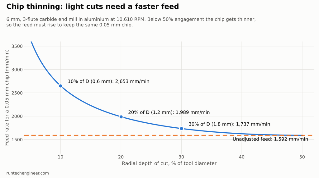
For the 6 mm tool in the example:
| Radial depth of cut | % of diameter | RCTF | Feed for a 0.05 mm chip |
|---|---|---|---|
| 3.0 mm | 50% | 1.00 | 1,592 mm/min |
| 1.8 mm | 30% | 1.09 | 1,737 mm/min |
| 1.2 mm | 20% | 1.25 | 1,989 mm/min |
| 0.6 mm | 10% | 1.67 | 2,653 mm/min |
This is why adaptive and trochoidal toolpaths, which take a narrow stepover at full depth, run at feed rates that look surprisingly high. See CNC toolpath programming for how those strategies work.
Starting Feeds and Speeds by Material
These are starting points for a solid carbide end mill of about 6 mm (1/4 inch) diameter, taken from Harvey Tool’s general machining guidelines and converted to metric. Surface speed stays the same for other tool sizes; chip load grows roughly in proportion to the tool diameter.
| Material | Surface speed (m/min) | Surface speed (SFM) | Chip load, 6 mm tool (mm/tooth) |
|---|---|---|---|
| Aluminium alloys | 150–305 | 500–1,000 | 0.05 |
| Polycarbonate and similar plastics | 60–150 | 200–500 | 0.075 |
| Low-carbon and low-alloy steel (1018, 1045) | 30–90 | 100–300 | 0.038 |
| Austenitic stainless steel (304) | 30–75 | 100–250 | 0.013 |
| Titanium (Ti-6Al-4V) | 15–75 | 50–250 | 0.013 |
| Nickel alloys (Inconel 718) | 12–18 | 40–60 | 0.025 |
Always check the chart for the exact tool you bought. Coating, flute count, helix angle, and tool length change the numbers, and the tool maker’s figure beats any general table.
Use the low end of the range when:
- the machine is light, such as a hobby router or a small benchtop mill;
- the tool sticks out far from the holder;
- the part is thin or poorly clamped;
- there is no coolant, or chips cannot clear easily, as in a deep slot.
Depth of Cut and Width of Cut
Feeds and speeds set how fast the tool works; depth and width of cut set how much it takes. Two choices dominate:
- Full-width slotting loads the whole cutter at once. Use a shallower depth and the plain, unadjusted chip load.
- Side milling with a narrow stepover spreads wear along the flute length and lets you cut deeper. Use a larger axial depth, a stepover well under half the diameter, and the chip thinning correction above. This is the basis of modern high-efficiency toolpaths.
On a light machine, the limit is usually rigidity rather than the tool. If the machine chatters or the steppers stall, reduce the depth or width of cut before you reduce the chip load. A stepper machine that loses position at higher feeds may also need its motor tuning checked.
Choosing the Right Tool
The tool choice comes before the numbers, because the numbers depend on it.
| Choice | Use it for | Why |
|---|---|---|
| 2 or 3 flutes | Aluminium, plastics, slotting | Large flute space clears chips and avoids packing |
| 4 or more flutes | Steel, stainless, finishing | More edges share the load; less room needed for chips |
| Uncoated or ZrN / DLC coated, polished flutes | Aluminium | Reduces material sticking to the edge |
| TiAlN or AlTiN coated | Steel, stainless, titanium | Resists heat at higher cutting temperatures |
| Shortest tool that reaches | Everything | Each extra millimetre of stick-out adds deflection and chatter |
| Largest diameter that fits the features | Roughing | A larger tool is stiffer and removes material faster |
Internal corners limit the tool size: a pocket corner can never be sharper than the tool radius. Designing larger corner radii into the part, where the function allows, lets you use a bigger, faster tool.
Reading the Results: Signs of Wrong Feeds and Speeds
| What you see or hear | Likely cause | First thing to try |
|---|---|---|
| High-pitched squeal, powdery chips, shiny rubbed surface | Chip load too low | Raise the feed rate |
| Burnt or discoloured chips, glowing edge | Surface speed too high | Lower the RPM |
| Chatter marks and a loud, uneven sound | Too much depth or width, or too much stick-out | Reduce engagement; shorten the tool |
| Chipped cutting edges | Chip load too high, or vibration | Lower the feed; check clamping |
| Aluminium welded onto the tool | Speed too high without coolant, or chips recut | Add air blast or coolant; improve chip clearing |
| Tool snaps on entry | Too aggressive a plunge | Ramp or helix into the material |
Common Mistakes
- Running too slow “to be safe.” A low feed with a normal RPM makes a thin chip that rubs and dulls the tool faster than a proper cut.
- Ignoring chip thinning. Light finishing passes at the unadjusted chip load are a common cause of short tool life.
- Using the same numbers for every tool. A 3 mm tool and a 12 mm tool need very different chip loads in the same material.
- Forgetting the machine. A published chart assumes a rigid machine. Scale back on a light router, then work up.
- Never checking the program. Feed and speed appear in the program as the F and S words; see what G-code is. Run a toolpath simulation before cutting to catch a feed that is wrong by a factor of ten.
On a lathe, the same ideas apply, but the surface speed changes with the part diameter, so controls often hold it constant automatically. CNC milling vs CNC turning explains how the two machines differ.
Feeds and Speeds FAQ
How do you calculate feeds and speeds?
First find the RPM from the surface speed for your material: RPM = (1000 × Vc) ÷ (π × D). Then find the feed: feed rate = RPM × chip load × number of flutes. Take the surface speed and chip load from the tool maker’s chart.
What is chip load?
Chip load is the thickness of material each cutting edge removes in one revolution, in millimetres or inches per tooth. It is the main factor in tool life: too low and the tool rubs, too high and it chips or breaks.
What is the difference between feed rate and chip load?
Chip load is per tooth per revolution. Feed rate is how fast the whole tool moves, in mm/min or inches per minute. Feed rate equals chip load times the number of flutes times the RPM.
What is chip thinning?
When the stepover is less than half the tool diameter, the actual chip is thinner than the programmed chip load. To keep the intended chip, raise the feed using the radial chip thinning factor.
Why do my end mills wear out so fast?
The most common causes are a chip load that is too low (rubbing), a surface speed that is too high (heat), poor chip evacuation (recutting), and vibration from too much stick-out or a flexible setup.
Want Settings Matched to Your Machine?
RunTechEngineer selects tools and calculates feeds and speeds for each job, then checks the program in simulation before it reaches the machine. Explore our CAM programming services or contact us with your part, material, and machine.