To integrate sensors into existing machinery, decide what the data is for, choose the least invasive way to get it, match the sensor’s signal to whatever will read it, and stay away from the machine’s safety circuits. Most retrofits fail on the first and third points, not on the hardware.
This guide walks through the seven steps we follow when adding sensors to a machine that was never designed for them, whether that is a 30-year-old press, a manual lathe, or a CNC router.
Step 1: Decide What the Data Is For
Start with the decision, not the sensor. “We want to monitor the machine” is not a requirement. “We want a warning two weeks before the spindle bearing fails” is.
The question you are answering sets everything downstream:
| Question | What to measure | Typical sensor |
|---|---|---|
| Is the machine running or idle? | Motor current | Clamp-on current transformer |
| How many parts did it make? | Cycle events | Proximity or photoelectric sensor |
| Is a bearing wearing out? | Vibration | Accelerometer |
| Is it running hot? | Surface temperature | RTD or thermocouple |
| Is hydraulic or air pressure holding? | Line pressure | Pressure transmitter |
A run/idle signal needs one cheap sensor and a reading every few seconds. Bearing diagnostics need a much faster accelerometer and someone who can read a spectrum. Pick the simplest measurement that answers the question. Our guide to choosing the right sensor covers the trade-offs in more detail.
Step 2: Choose How Invasive the Retrofit Will Be
There are three ways to get data out of an existing machine. Always start with the least invasive one that works.
Level 1: Bolt-on sensors, no connection to the controls
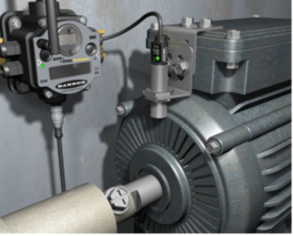
The sensor sits on the outside of the machine and has its own power and data path. A clamp-on current transformer goes around one motor lead without cutting it. A magnet-mount or stud-mount accelerometer goes on a bearing housing. A surface temperature probe is strapped to a gearbox.
Nothing in the control cabinet is touched, so the machine behaves exactly as before. This covers most monitoring projects and is where we recommend starting.
Level 2: Read signals the machine already has
Many machines already produce the signal you need: a cycle-complete relay, a stack light, a spindle-run contact, or data inside the PLC. You can read these through an isolated input (an optocoupler or interposing relay), or over the controller’s own network port if it has one.
This gives better data than bolt-on sensors, but you are now connected to the control system. Read-only and electrically isolated is the rule.
Level 3: Wire new sensors into the controller
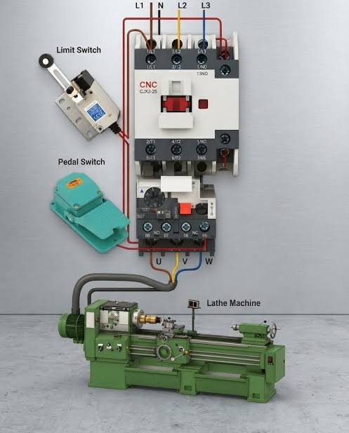
The new sensor becomes an input to the PLC or CNC and the control logic changes to use it. This is no longer monitoring; it is a modification to the machine. It needs the electrical drawings, a risk assessment, and someone qualified to change the program.
If your goal is visibility rather than new machine behavior, you rarely need Level 3.
Step 3: Find Safe Integration Points
Before any hardware goes on, get the machine’s electrical drawings and walk the machine with the person who maintains it. Then apply four rules.
- Never tap a safety circuit. Emergency stops, guard interlocks, light curtains, and two-hand controls are off limits. Do not parallel a wire onto them, do not share their power supply, and do not mount anything that blocks a guard.
- Isolate everything you read. Any connection to an existing signal goes through an optocoupler, an isolated input module, or a relay, so a fault in your monitoring hardware cannot reach the machine’s controls.
- Mount where the signal is, not where it is convenient. A vibration sensor belongs on the bearing housing, on a rigid, flat, clean surface, as close to the load path as you can get. On a sheet-metal cover it mostly measures the cover.
- Lock out before you open the cabinet. Follow your site’s lockout/tagout procedure for any work inside an enclosure or near moving parts, including a “quick” clamp-on install.
Step 4: Match the Signal to What Reads It
Older machines mix voltages and signal types, and a sensor that is electrically wrong for its input will either read garbage or damage something. Check these before ordering.
| Signal type | Where you meet it | What to check |
|---|---|---|
| 24 V DC switching (PNP or NPN) | Proximity and photoelectric sensors | Whether the input expects PNP (sourcing) or NPN (sinking) |
| 4–20 mA current loop | Pressure, temperature, and level transmitters | Loop power supply and the input’s load resistor |
| 0–10 V analog | Older drives and position sensors | Cable length and noise; voltage signals degrade over distance |
| IO-Link | Newer smart sensors | Needs an IO-Link master; unshielded 3-wire cable, up to 20 m per sensor |
| Modbus RTU over RS-485 | Power meters, drives, many transmitters | Baud rate, address, termination resistors |
For a retrofit, 4–20 mA is usually the safest analog choice. Current does not drop over long cable runs, and because the signal’s zero is 4 mA instead of 0 mA, a broken wire reads as a fault, not as a valid measurement. Transmitters that follow the NAMUR NE 43 recommendation go further and signal a sensor failure with a current of 3.6 mA or less, or 21 mA or more.
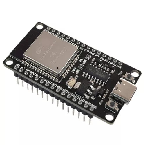
If the sensor feeds a microcontroller instead of a PLC, mind the logic level. An ESP32 input is 3.3 V and will not survive a 24 V signal without a level shifter or optocoupler. We cover the controller side in embedded systems development and compare common boards in ESP32 vs Arduino.
Step 5: Protect the Signal from Noise
A machine with a variable frequency drive (VFD), servo drives, or large contactors is an electrically noisy place. A reading that jumps whenever the spindle starts is almost always a wiring problem, not a bad sensor.
- Use shielded twisted-pair cable for analog signals, and connect the shield to ground at one end only, normally the cabinet end.
- Route sensor cables away from motor and VFD output cables. Where they must cross, cross at 90 degrees.
- Give the sensors their own clean 24 V supply instead of borrowing from a supply that also feeds solenoids or contactors.
- Prefer current-loop or digital signals over 0–10 V for anything longer than a few meters.
- Check the sensor’s IP rating against coolant, oil mist, and chips, and add strain relief wherever the cable moves.
Step 6: Get the Data Off the Machine
The sensor needs something to read it and somewhere to send the result. For a retrofit, keep this layer separate from the machine’s own controller.
A small edge device (an industrial gateway, a compact PLC, or a microcontroller board in a proper enclosure) reads the sensors, timestamps the values, and forwards them over Ethernet or Wi-Fi. MQTT is the common choice for sending readings to a server or cloud platform, and Modbus TCP or OPC UA are common when the data goes to an existing SCADA system.
Two practical points:
- Keep the machine off the open internet. Put the gateway on its own network segment and let it push data outward. Nothing outside should be able to reach in to the machine.
- Buffer locally. Networks on a shop floor drop. A gateway that stores readings and sends them when the link returns saves you from gaps in the history.
Once data is flowing, it needs a screen and a set of rules. See our guides to remote monitoring dashboards and automation and alerts.
Step 7: Commission and Set a Baseline
A sensor that is installed is not yet a sensor you can trust. Before anyone acts on the data:
- Check each reading against a reference: a clamp meter for current, a handheld thermometer for temperature, a gauge for pressure.
- Run the machine through its normal states (off, idle, light load, full load) and confirm the readings move the way they should.
- Record one to two weeks of normal operation before setting any alarm limits. Thresholds copied from a datasheet produce false alarms; thresholds based on this machine’s own baseline do not.
- Confirm the machine behaves exactly as it did before, including cycle time and every safety function.
- Update the electrical drawings and label the new cables and devices.
When a Retrofit Becomes a Machine Modification
Adding monitoring that only observes the machine is generally not treated as changing it. Changing how the machine is controlled or protected can be.
In the European Union this now has a legal definition. Regulation (EU) 2023/1230, which applies from 20 January 2027, defines a substantial modification as a physical or digital change that the manufacturer did not foresee, that creates a new hazard or increases an existing risk, and that requires new guards or protective devices involving changes to the safety control system, or extra measures for stability or strength. Under Article 18, whoever makes such a modification is treated as the manufacturer and takes on the manufacturer’s obligations.
Other countries have their own rules, and machine warranties and insurance policies often have conditions too. If your retrofit goes beyond bolt-on monitoring, check with the machine builder or a machinery safety specialist first. This article is general guidance, not legal advice.
Common Mistakes
- Starting with too many sensors. Instrument one machine and one question first, prove the data is useful, then expand.
- Mounting for convenience. A sensor in the wrong place produces confident, wrong numbers.
- Sharing a noisy power supply. This is the most common cause of readings that jump when a motor starts.
- Setting alarms on day one. Without a baseline, operators learn to ignore the alerts within a week.
- Leaving no documentation. The next technician who opens the cabinet needs to know what the extra wires are.
Frequently Asked Questions
Can you add sensors to a machine that has no PLC?
Yes. Bolt-on sensors do not need the machine to have any controller at all. A current clamp on the motor lead and a small gateway are enough to track running time, idle time, and load on a fully manual machine.
Will adding sensors void the machine’s warranty or certification?
External, non-invasive sensors that do not connect to the controls usually do not, but the terms differ by manufacturer, so check before you start. Anything wired into the control or safety system is a different matter and should be cleared with the machine builder.
What is the easiest sensor to start with?
A clamp-on current transformer on the main motor. It installs without cutting any wire, and motor current alone tells you whether the machine is off, idle, or cutting, which is enough to calculate utilization.
Do I need an internet connection?
No. The data can stay on a local server or a panel PC on the shop floor. An internet connection is only needed if you want to view it remotely or use a cloud platform.
Have Existing Equipment You Want to Modernize?
RunTechEngineer adds sensors and connectivity to existing machines, from single-machine run/idle monitoring to full retrofits. For an example of the mechanical and electrical work behind a complete build, see our 3-axis CNC machine project. Explore our IoT services, or contact us with the machine type and what you want to measure.