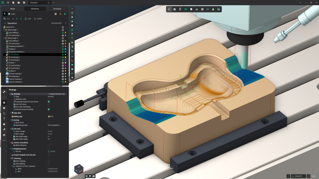
CNC toolpath programming is the step where you decide how the cutter moves through the material: which tool, in what order, along what path, and how much it removes on each pass. The CAD model only describes the finished shape. The toolpath is the plan for getting there.
Good toolpath programming comes down to one habit: rough with a strategy that keeps the load on the tool steady, then finish with a strategy matched to the shape of each surface. This guide explains the common strategies and how to choose between them.
What a Toolpath Is
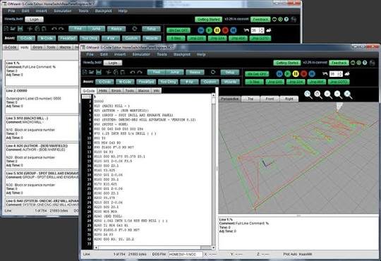
A toolpath is the route the tip of the cutting tool follows, together with the feed rate, spindle speed, and depth for each move. CAM software calculates it from the 3D model and the choices you make, then converts it to G-code the machine can run. If you are new to the process, start with what CAM is.
The same part can be programmed in many ways. Two programs that produce an identical part can differ widely in cycle time and tool wear, which is why the choice of strategy matters.
The Toolpath Programming Workflow
- Review the model. Look for features that are hard to machine: deep narrow pockets, sharp internal corners, thin walls, undercuts. Fixing them in the design is cheaper than programming around them, which is the purpose of design for manufacturing.
- Plan the setups. Decide how the part is held and how many times it must be turned over. Fewer setups mean less time and better accuracy between features.
- Define the stock and the work zero. Tell the software the size of the raw material and where the machine’s reference point is.
- Rough. Remove most of the material quickly, leaving a thin, even layer for finishing.
- Semi-finish and finish. Bring each surface to final size and surface quality.
- Drill, tap, chamfer, and deburr.
- Simulate. Check for collisions, gouges, and leftover material with toolpath simulation before cutting anything.
- Post-process. Convert the toolpaths to code for your specific controller; see post-processing.
Roughing Toolpaths
Roughing removes the bulk of the material. Speed matters here, surface finish does not, and the goal is to leave a uniform skin of material for the finishing tool.
Pocket (offset) roughing
The traditional approach clears material layer by layer with paths offset from the shape of the pocket. It is simple and works on any machine, but the tool load spikes in corners, where the cutter is suddenly engaged with far more material. That forces you to program conservatively for the worst corner.
Adaptive clearing
Adaptive clearing, also sold as high-efficiency or trochoidal milling, adjusts the path so the load on the tool stays stable. Because the load never spikes, you can cut much deeper, using most of the flute length, with a small sideways step and a higher feed rate. The result is usually shorter cycle times and longer tool life, especially in steel, stainless, and deep pockets.
It is the default choice for roughing on modern CAM systems. Pocket roughing is still reasonable for shallow features, soft materials, and older controllers that struggle with the many short moves adaptive paths generate.
Finishing Toolpaths
Finishing strategies are chosen by the shape of the surface. No single strategy finishes a whole 3D part well, so most programs combine two or three.
2D toolpaths for prismatic parts
Parts made of flat faces and vertical walls need only 2D strategies:
- Face: flattens the top of the stock.
- 2D contour: follows the outline of a wall or the outside of the part.
- 2D pocket: clears and finishes an enclosed area with a flat floor.
- Drilling cycles: spot, drill, peck drill, tap, and bore.
- Chamfer and deburr: break the sharp edges.
3D toolpaths for contoured surfaces
| Strategy | How it moves | Best for |
|---|---|---|
| Parallel (raster) | Straight parallel passes that follow the surface up and down | Shallow, gently curved areas |
| Contour (constant Z, waterline) | Level-by-level passes around the part | Steep walls |
| Scallop (constant stepover) | Passes spaced evenly along the surface itself | Even finish across mixed slopes; rest finishing |
| Horizontal | Finds flat areas and clears them | Flat floors and ledges |
| Pencil | Traces internal corners and small fillets | Cleaning up corners after other finishing passes |
| Spiral, radial | Spiral or spoke-like passes from a center point | Round, shallow shapes |
The classic combination is contour passes on the steep walls and parallel passes on the shallow areas, with a pencil pass to clean the corners. Parallel passes alone leave a poor finish on steep walls, and contour passes alone leave wide steps on shallow areas.
Rest machining
A large tool roughs quickly but cannot reach into small corners. Rest machining tells the software to cut only the material the previous tool left behind, so a smaller tool does not waste time recutting air.
Turning and Multi-Axis Toolpaths
On a lathe the part spins and the tool moves in two axes, so the strategies are simpler: facing, rough turning, finish turning, grooving, threading, boring, and parting off. The main decisions are depth of cut per pass and the order of operations so the part stays rigid as material comes off. We compare the two processes in CNC milling vs CNC turning.
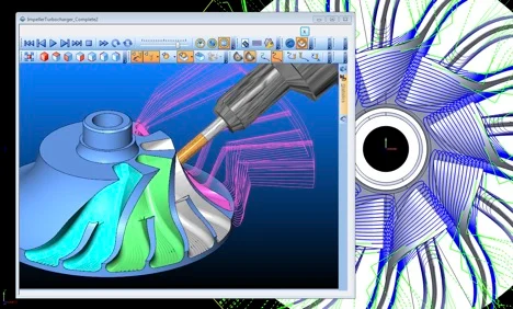
Multi-axis machining comes in two forms. In 3+2 (positional) machining, the rotary axes tilt the part to a fixed angle and ordinary 2D and 3D strategies run from there. This reaches most angled features and reduces setups. In simultaneous 5-axis machining, the tool orientation changes continuously during the cut, which is needed for impellers, turbine blades, and deep undercuts. It demands careful collision checking between the tool, holder, part, and fixture.
How to Choose a Toolpath Strategy
| Feature | Roughing | Finishing |
|---|---|---|
| Flat top face | Face | Face |
| Outside profile with vertical walls | Adaptive clearing | 2D contour |
| Pocket with flat floor | Adaptive clearing | 2D pocket or contour, then floor pass |
| Steep 3D walls | Adaptive clearing | Contour |
| Shallow 3D surface | Adaptive clearing | Parallel or scallop |
| Mixed steep and shallow surface | Adaptive clearing | Contour plus parallel, or scallop |
| Tight internal corners | Rest machining with a smaller tool | Pencil |
| Holes | Drill or helical bore | Ream or bore if a tight tolerance is needed |
The Parameters That Shape a Toolpath
The strategy sets the pattern. These settings decide how it actually cuts.
- Stepdown (axial depth): how deep the tool cuts on each level.
- Stepover (radial width): how far the tool moves sideways between passes. In finishing, a smaller stepover gives a smoother surface and a longer cycle.
- Stock to leave: the layer roughing leaves for finishing. Too little and the finish tool rubs or the roughing marks show; too much and the finish tool is overloaded.
- Cut direction: in climb milling the cutter rotates with the feed direction, and in conventional milling against it. Climb milling is the usual choice on CNC machines and generally gives a better finish. Conventional milling is safer on machines with backlash, such as older or manual mills, and can be more accurate on finish passes when the tool is prone to deflecting.
- Entry method: plunging straight down is hard on most end mills. Ramping or a helical entry eases the tool into the material.
- Lead-in and lead-out: arcs that bring the tool onto and off the wall smoothly, so it does not leave a mark where the cut starts.
- Tolerance and smoothing: how closely the path follows the model. A tighter tolerance means a more accurate surface, a larger program, and sometimes a slower machine.
Spindle speed and feed rate depend on the tool and the material. We cover those in our guide to feeds and speeds.
Common Toolpath Programming Mistakes
- Finishing everything with one strategy. A single parallel pass over a part with steep walls leaves visible steps on those walls.
- Uneven stock for the finish pass. If roughing leaves 0.2 mm in one place and 2 mm in a corner, the finish tool deflects and the corner comes out oversize. A semi-finish pass fixes this.
- Plunging a tool that cannot plunge. Use a ramp or helix, or pre-drill.
- Ignoring the tool holder. The cutter may clear the part while the holder hits a wall. Include the holder in the simulation.
- Too many setups. Each time the part is re-clamped, some accuracy is lost.
- Skipping simulation. A collision on screen costs nothing.
- Using a generic post-processor. Code that is almost right for your controller is how machines crash.
Frequently Asked Questions
What is toolpath programming in CNC?
It is the process of defining how the cutting tool moves to turn raw stock into the finished part: the tools, the order of operations, the path of each cut, and the cutting parameters. It is done in CAM software and output as G-code.
What is the difference between roughing and finishing toolpaths?
Roughing removes most of the material as fast as possible and leaves a small allowance. Finishing removes that allowance with light, precise cuts to reach the final size and surface quality.
What is adaptive clearing?
A roughing strategy that keeps the load on the tool stable by controlling how much of the cutter is engaged with the material. It allows deeper cuts and higher feed rates than traditional pocket roughing.
Is climb or conventional milling better?
Climb milling for most CNC work, because it usually gives a better finish and tool life. Conventional milling is the safer choice on machines with backlash and is sometimes used for finish passes with long or thin tools.
Which software is used for toolpath programming?
Common CAM packages include Autodesk Fusion, Mastercam, SolidCAM, and the free FreeCAD CAM workbench. The strategy names differ slightly between them, but the ideas in this guide apply to all.
Need Toolpaths Programmed for Your Part?
RunTechEngineer programs toolpaths for milling, turning, and multi-axis work, matched to your part, your material, and your machine’s controller. See our CAM programming services, or contact us with your model and machine details.