Mechanical failure analysis is the process of finding out why a part broke, bent, or wore out, so the same failure does not happen again. It works like an investigation: collect the evidence, read what the part itself shows, test each possible cause, and only then decide what to change.
This guide explains the process step by step, the main failure modes and the signs each one leaves, the tests used to confirm the cause, and where FEA fits. If you want to check a design before anything breaks, see our guide to predicting mechanical failure with FEA instead.
The Short Answer
- Find the mechanism first, then the root cause. “It broke by fatigue” is the mechanism. “A sharp corner at the keyway, plus vibration from a misaligned coupling” is the root cause.
- Protect the evidence. Photograph the part where it failed, keep every piece, and never fit the broken halves back together.
- Test hypotheses instead of guessing. Hardness tests, a look at the fracture surface, and a stress check each rule causes in or out.
- Fix the cause, not the symptom. Replacing a part with a stronger copy often moves the failure somewhere else.
Failure Mode vs Root Cause
The failure mode, or mechanism, describes how the part failed: fatigue, overload, wear, corrosion, or creep. The root cause explains why that mechanism happened in this part, in this machine, at this time.
A common example is a shaft that cracks by fatigue at a screw thread. The fracture surface shows the mechanism clearly. It does not tell you whether the thread root was too sharp, the load was higher than designed, the material was too soft, or the shaft was bent by a misaligned bearing. That takes a design review and a look at how the machine was actually used. Many failures also have more than one root cause acting together.
The Failure Analysis Process, Step by Step
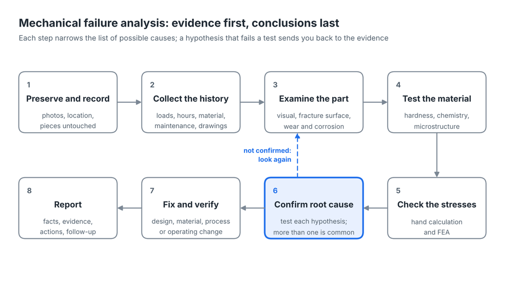
Most structured methods follow the same order. Each step narrows the list of possible causes before the next, more expensive step begins.
1. Preserve and Record the Evidence
Photograph the failed part where it failed, before anything is moved or cleaned. Record where each piece was found, and keep all of them. Do not touch the fracture surface or fit the broken pieces together: rubbing the halves destroys the fine marks that show how the crack grew.
2. Collect the History
Gather everything known about the part: drawings and material specification, how it was made, how long it ran, the loads and speeds, any recent changes, and maintenance records. Talk to the people who operate the machine. An unfailed part from the same batch is valuable for comparison.
3. Examine the Part
Start with the naked eye and a magnifier, then move to a microscope if needed. Look for distortion, wear, corrosion, and the fracture surface itself. The surface often shows the failure mode and where the crack started (see the table below).
4. Test the Material
Check that the part is made of what the drawing says. A hardness test is quick and shows whether the heat treatment was right. Chemical analysis confirms the alloy. A metallographic section, cut, polished, and etched, shows the microstructure and defects such as porosity or inclusions.
5. Check the Stresses
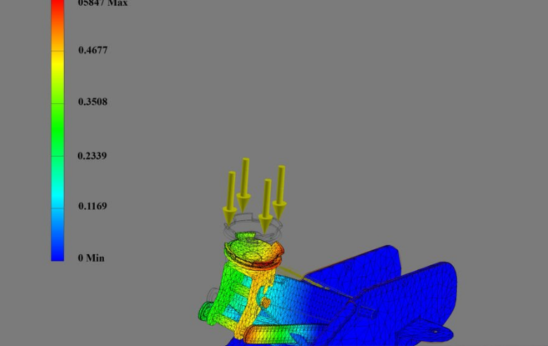
Compare the stress at the crack origin with the strength of the material. A hand calculation is often enough. FEA helps when the geometry is complex or the load path is unclear, and it is a good way to test “what if” questions: what if the support was misaligned, or the load was twice the design value?
6. Confirm the Root Cause
List every possible cause and check each one against the evidence. A cause stays on the list only if it explains everything you found. If none fits, go back to the part and look again.
7. Fix and Verify
The fix may be a design change, a different material or heat treatment, a manufacturing change, or a change in how the machine is operated. Verify it: by calculation, by test, or by watching the next parts in service.
8. Report
Write down the facts, the evidence behind each conclusion, and the actions taken. A short, factual report keeps the next failure from being investigated from scratch.
Common Mechanical Failure Modes and Their Signs
| Failure mode | What you usually see | Typical causes |
|---|---|---|
| Ductile overload | Bending, stretching, or necking before the break; dull, fibrous surface; 45° shear lips | Load far above design, wrong material, part too small |
| Brittle overload | Little or no distortion; pieces fit back together; chevron marks point to the origin | Low temperature, very hard or embrittled material, sharp notch, impact |
| Fatigue | Smooth zone with beach marks, then a rough final zone; little distortion | Repeated loading at a stress raiser: sharp corners, threads, holes, weld toes |
| Wear | Gradual loss of material, scoring, polished or pitted contact surfaces, debris in the lubricant | Poor lubrication, contamination, overload of contact surfaces, misalignment |
| Corrosion | Rust or deposits, pits, thinning; with stress, branching cracks in an otherwise ductile part | Moisture, chemicals, wrong material or coating for the environment |
| Creep | Slow, permanent stretching or sagging over time, often with no single event | Sustained load at high temperature; plastics creep even at room temperature |
| Buckling | A slender member bent or kinked sideways, usually without fracture | Compression load above the critical load, slender design, side load |
Fatigue deserves special attention: about half of all fractures in service are fatigue fractures, and they happen under normal operating loads. Our article on fatigue failure explains how to recognize one in detail.
Reading a Fracture Surface
The fracture surface is the most useful piece of evidence. Three questions get you most of the way:
- Where did it start? Beach marks and chevron marks point back to the origin. The origin is usually at a stress raiser such as a corner, a thread, a hole, a weld, or a defect.
- How fast did it grow? A smooth zone means slow, cyclic growth, which is fatigue. A rough or fibrous surface across the whole break means a single overload.
- How big was the final break? In a fatigue failure, the size of the rough final zone shows the load. A small final zone means low stress over many cycles; a large one means high stress.
Keep the surface clean and dry. Wire brushes, files, and acid cleaners destroy the marks you need to read.
Tests Used in Failure Analysis
| Test | What it tells you | Damages the part? |
|---|---|---|
| Visual and microscope examination | Failure mode, origin, distortion, wear, corrosion | No |
| Dye penetrant or magnetic particle inspection | Other cracks not yet visible, in the failed part or its sister parts | No |
| Hardness test | Whether the heat treatment and strength are as specified | Very small mark |
| Chemical analysis | Whether the alloy matches the specification | Small sample |
| Metallography | Microstructure, grain size, porosity, inclusions, crack path | Yes, a section is cut |
| Scanning electron microscopy (SEM) | Fine fracture features that confirm fatigue, overload, or embrittlement | Small sample |
| Stress analysis (hand calculation or FEA) | Whether the design or the load can explain the failure | No |
The usual order is from non-destructive to destructive, so evidence is not lost before it is recorded.
Where FEA Fits After a Failure
FEA does not find the cause on its own, but it is a strong way to test a hypothesis. Model the part with the loads you believe it saw, and check whether the highest stress sits where the crack started. If the peak stress is somewhere else, the assumed load or support is probably wrong.
FEA is also how the fix is checked. A larger fillet radius or a thicker section can be compared before anything is machined. For cyclic loads, the stress result feeds a fatigue analysis. Whatever the model, check that the stress at the origin does not change when the mesh is refined; our guide to mesh convergence shows how.
Failure Analysis for Plastic and 3D Printed Parts
Plastic parts fail in some ways metal parts rarely do:
- Layer separation. A 3D printed part is weakest between its layers. A break that follows a layer line points to print orientation or layer bonding, not the material itself.
- Creep and heat. Plastics creep under steady load at room temperature, and soften sharply near their glass transition temperature. A clip that slowly opened, or a bracket that sagged in a hot car, is a creep or heat failure.
- Moisture and chemicals. Some plastics absorb water or are attacked by solvents and oils, which lowers their strength over time.
For printed parts, the fix is often orientation, wall count, or a different filament rather than a thicker part. See best infill for strength and PETG vs ABS for the material side.
Common Mistakes in Failure Analysis
- Fitting the broken halves together to “see how it fits”, which damages the fracture surface.
- Cleaning the part with a wire brush or solvent before it is photographed and examined.
- Stopping at the first plausible cause instead of checking it against all the evidence.
- Calling the mechanism the root cause: “fatigue” is not an answer on its own.
- Replacing the part with a stronger one without understanding why it failed, which can move the failure to a more expensive part.
- Ignoring the sister parts: if one failed, others from the same batch or machine may be cracking too.
Mechanical Failure Analysis FAQ
What is mechanical failure analysis?
It is the investigation of a failed mechanical part to find how it failed and why. It combines examination of the part, material tests, and stress analysis, and ends with an action that prevents a repeat.
What is the difference between a failure mode and a root cause?
The failure mode is how the part failed, for example fatigue or overload. The root cause is why: a design detail, a material problem, a manufacturing defect, or how the part was used.
What is the most common cause of mechanical failure?
Fatigue. About half of all fractures in service are fatigue fractures, and they usually start at a stress raiser such as a sharp corner, a thread, or a weld.
Can FEA find the cause of a failure?
Not by itself. FEA tests a hypothesis: if the modeled peak stress sits at the crack origin and exceeds what the material can take, the assumed load and geometry explain the failure. It is also used to check the fix.
What should I do with a broken part before analysis?
Photograph it where it failed, keep every piece, and store the pieces dry and separately. Do not clean the fracture surface or fit the halves together.
Need to Find Out Why a Part Failed?
RunTechEngineer can review the broken part or photos of it, check the stresses with hand calculations and FEA, and redesign the part so the failure does not return. Explore our FEA services or Contact Us to discuss your failure.