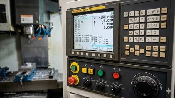
What is G-code? It is the language a CNC machine reads to know where to move, how fast to go, and what to switch on or off. This guide explains how to read a line of G-code, then gives a full G-code list and M-code list grouped by job, a short program explained line by line, and the codes a 3D printer uses.
What Is G-Code?
G-code is the programming language that CNC machines understand. Each line, called a block, is a short instruction: move to this point, cut at this speed, start the spindle, change the tool. A program is a list of these blocks, run one after another, that turns a block of raw material into a finished part.
If a CNC machine is the body, G-code is the set of directions it follows. The machine does not know what the part should look like. It only knows the next position it has been told to reach.
The language was standardised as RS-274 in the United States and later as ISO 6983. Every controller builder has since added its own codes, so treat any G-code list, including this one, as the common core rather than the exact rules for your machine.
How to Read a Line of G-Code
A typical line looks like this:
N40 G01 X50.0 Y25.0 Z-2.0 F300.Read from left to right: line number 40, move in a straight line (G01) to X 50 mm, Y 25 mm, Z 2 mm below the work surface, at a feed rate of 300 mm per minute. Each part of the line is a word: one letter followed by a number. The letter says what kind of value it is.
| Letter | Meaning |
|---|---|
| N | Line (block) number, optional |
| G | Preparatory command: type of motion, units, plane, offset, cycle |
| M | Machine function: spindle, coolant, tool change, program stop |
| X, Y, Z | Target position on each linear axis |
| A, B, C | Target angle on a rotary axis |
| I, J, K | Arc centre, measured from the arc’s start point |
| R | Arc radius, or the retract height in a drilling cycle |
| F | Feed rate, the speed of a cutting move |
| S | Spindle speed in revolutions per minute |
| T | Tool number |
| H, D | Tool length offset number and cutter radius offset number |
| P, Q | Extra values: dwell time, peck depth, subprogram number |
| O | Program number |
Comments sit inside round brackets, for example (6 MM END MILL). The controller ignores them; they are for the person reading the program.
Modal and Non-Modal Codes
Most G-codes are modal. Once a modal code is set, it stays active until another code from the same group replaces it. That is why many lines in a real program carry only coordinates:
G01 X50.0 F300.
Y20.0
X0
The second and third lines are still straight cutting moves at 300 mm/min, because G01 and F300 are still active. Non-modal codes, such as G04 (dwell) or G53 (move in machine coordinates), act only on the line where they appear.
This is the most important idea for anyone learning to read G-code. A line never stands alone. To know what it does, you must know which modes are active from the lines above it.
G-Codes vs M-Codes
The name “G-code” is used for the whole language, but a program mixes two families of commands. G-codes describe geometry and motion: where the tool goes and how it travels. M-codes control the machine itself: spindle, coolant, tool changer, program stops. A working program always needs both.
G-Code List: The Codes You Will Actually See
The G-code list below covers the codes that appear in most milling programs written for Fanuc-style controls, which is also the style most CAM post-processors produce and what Mach3 and LinuxCNC follow. Codes are grouped by job. Leading zeros do not matter: G1 and G01 are the same command.
Motion
| Code | What it does |
|---|---|
| G00 | Rapid move to a position, used for repositioning, never for cutting |
| G01 | Straight-line cutting move at the programmed feed rate (F) |
| G02 | Clockwise arc, defined by end point plus radius (R) or centre (I, J, K) |
| G03 | Counterclockwise arc, same format as G02 |
| G04 | Dwell: pause for a set time (the unit of P differs between controls) |
Plane and units
| Code | What it does |
|---|---|
| G17 | Select the XY plane for arcs and cycles (the default on mills) |
| G18 | Select the XZ plane (the usual plane on lathes) |
| G19 | Select the YZ plane |
| G20 | Units in inches |
| G21 | Units in millimetres |
Positioning mode
| Code | What it does |
|---|---|
| G90 | Absolute positioning: coordinates are measured from the work zero |
| G91 | Incremental positioning: coordinates are measured from the current position |
| G28 | Return to the machine reference (home) position, through an intermediate point |
| G30 | Return to a second reference position, often used for tool change |
| G53 | Move in machine coordinates for this line only |
Work offsets
| Code | What it does |
|---|---|
| G54 to G59 | Select one of six work coordinate systems (where the part zero is) |
| G92 | Shift the coordinate system so the current position takes the values given |
| G10 | Write offset or tool data from inside the program (format varies by control) |
Tool compensation
| Code | What it does |
|---|---|
| G40 | Cancel cutter radius compensation |
| G41 | Cutter radius compensation, tool to the left of the path |
| G42 | Cutter radius compensation, tool to the right of the path |
| G43 | Apply tool length offset, number given by H |
| G49 | Cancel tool length offset |
Canned cycles (drilling, tapping, boring)
A canned cycle packs a whole drilling sequence into one line. Once active, every following X/Y position drills another hole until G80 cancels it.
| Code | What it does |
|---|---|
| G73 | High-speed peck drilling with short chip-breaking retracts |
| G81 | Simple drilling: feed to depth, rapid out |
| G82 | Drilling with a dwell at the bottom, for spot faces and counterbores |
| G83 | Deep-hole peck drilling, full retract after each peck (Q) |
| G84 | Right-hand tapping |
| G85 | Boring: feed in, feed out |
| G89 | Boring with a dwell at the bottom, feed out |
| G80 | Cancel the active canned cycle |
| G98 | After each hole, return to the starting height |
| G99 | After each hole, return only to the R plane |
Feed and spindle modes
| Code | What it does |
|---|---|
| G93 | Inverse time feed, mainly for 4- and 5-axis moves |
| G94 | Feed in units per minute (the normal mode on mills) |
| G95 | Feed in units per spindle revolution (common on lathes) |
| G96 | Constant surface speed, spindle speed changes with diameter (lathes) |
| G97 | Constant spindle speed in RPM |
Path control
| Code | What it does |
|---|---|
| G61 | Exact stop mode: the machine reaches every corner exactly |
| G64 | Path blending mode: the machine rounds corners slightly to keep moving |
On a lathe
Lathe programs use the same core codes with a few differences. X is usually programmed as a diameter, not a radius. G18 is the working plane. Lathes add roughing and finishing cycles (G71 and G70 on Fanuc-style controls) and a threading cycle (G76). See CNC milling vs CNC turning for how the two machines differ.
M-Code List
M-codes vary more between machines than G-codes, because each builder wires them to its own hardware. These are the ones almost every mill understands.
| Code | What it does |
|---|---|
| M00 | Program stop; the operator presses cycle start to continue |
| M01 | Optional stop; stops only if the Optional Stop switch is on |
| M02 | End of program |
| M03 | Spindle on, clockwise, at the speed set by S |
| M04 | Spindle on, counterclockwise |
| M05 | Spindle stop |
| M06 | Tool change to the tool set by T |
| M07 | Mist coolant on |
| M08 | Flood coolant on |
| M09 | Coolant off |
| M19 | Spindle orient (stop at a fixed angle) |
| M30 | End of program and rewind to the start |
| M98 | Call a subprogram (P gives the program number) |
| M99 | Return from a subprogram |
Many controls let you add your own M-codes. In Mach3, for example, M6 runs a macro script you can edit, and you can write new M-code macros for probing or tool setting. Our guide to Mach3 custom macros and screen sets shows how.
A Short G-Code Program, Line by Line
This program cuts a 1 mm deep slot with a 6 mm end mill: a straight line, a quarter arc, then another straight line. Work zero (G54) is the lower-left corner of the part, on its top surface.
%
O1001 (SLOT DEMO)
G21 G17 G40 G49 G80 G90
T1 M06 (6 MM FLAT END MILL)
G54
S3000 M03
G00 X10.0 Y10.0
G43 H01 Z5.0
M08
G01 Z-1.0 F100.
G01 X50.0 F300.
G03 X70.0 Y30.0 R20.0
G01 Y50.0
G00 Z5.0
M09
M05
G91 G28 Z0
G90
M30
%| Line | What it does |
|---|---|
| % and O1001 | Start of the file and the program number, with a name in brackets |
| G21 G17 G40 G49 G80 G90 | Safety line: millimetres, XY plane, no cutter or length compensation, no canned cycle, absolute positions |
| T1 M06 | Load tool 1 |
| G54 | Use work offset 1, the part zero set by the operator |
| S3000 M03 | Spindle on clockwise at 3,000 RPM |
| G00 X10.0 Y10.0 | Rapid to the start of the slot, still above the part |
| G43 H01 Z5.0 | Apply length offset 1 and rapid down to 5 mm above the surface |
| M08 | Flood coolant on |
| G01 Z-1.0 F100. | Feed down into the material at 100 mm/min |
| G01 X50.0 F300. | Cut a straight line 40 mm long at 300 mm/min |
| G03 X70.0 Y30.0 R20.0 | Cut a counterclockwise quarter arc of 20 mm radius, centre at X50 Y30 |
| G01 Y50.0 | Cut straight up to Y50 |
| G00 Z5.0 | Rapid out of the slot |
| M09, M05 | Coolant off, spindle stop |
| G91 G28 Z0 | Send Z home (the common Fanuc-style way to write it) |
| G90 | Back to absolute mode |
| M30 | End the program and rewind |
The arc could also be written with its centre instead of its radius: G03 X70.0 Y30.0 I0 J20.0. I and J are measured from the start of the arc (X50 Y10) to the centre (X50 Y30).
A drilling cycle looks like this. It drills three holes 8 mm deep, starting each one from 2 mm above the surface:
G98 G81 X20.0 Y15.0 Z-8.0 R2.0 F120.
X40.0
X60.0
G80
The first line sets the cycle and drills the first hole. Each following position drills another hole. G80 cancels the cycle so the next move does not drill by mistake. For deeper holes, G83 with a peck depth (for example Q2.0) clears chips as it goes.
G-Code for 3D Printers
FDM 3D printers also run G-code, produced by a slicer instead of CAM software. The motion codes are the same (G0, G1, G28, G90, G91, G92), but printers add codes for temperature, fans, and the extruder, which is driven as an extra axis called E. These are from Marlin, the most common printer firmware:
| Code | What it does on a printer |
|---|---|
| G28 | Home all axes |
| G29 | Probe the bed and turn on bed levelling |
| G1 X Y E | Move while pushing out filament (E is the filament length) |
| G92 E0 | Reset the extruder position to zero |
| M104 / M109 | Set hotend temperature / set it and wait |
| M140 / M190 | Set bed temperature / set it and wait |
| M106 / M107 | Part-cooling fan on (speed by S) / off |
| M82 / M83 | Extruder in absolute / relative mode |
| M84 | Turn off the stepper motors |
A typical start sequence heats the bed and nozzle, waits, then homes:
M140 S60 ; bed to 60 °C
M104 S210 ; nozzle to 210 °C
M190 S60 ; wait for the bed
M109 S210 ; wait for the nozzle
G28 ; home all axes
G92 E0 ; reset extruder
Printer comments start with a semicolon. Some codes mean something completely different on a printer: in Marlin, M30 deletes a file from the SD card and G10 retracts filament, while on a CNC mill M30 ends the program and G10 writes offsets. Never send a printer program to a CNC machine, or the reverse. If you are choosing a printing process, see FDM vs SLA.
Why the Same Program Does Not Run on Every Machine
G-code is standardised only loosely, and each controller has its own dialect. A program written for a Fanuc control may fail or behave differently on a Haas, a Siemens, a Heidenhain, or a hobby controller such as Mach3. Common differences:
- Code meanings. G76 is a fine boring cycle on Fanuc-style mills but a threading cycle on lathes and in LinuxCNC.
- Units of a value. The P in G04 is milliseconds on some controls and seconds on others, so P500 can mean half a second or more than eight minutes.
- Tool change and cycle formats. Each builder sequences tool changes, probing, and canned cycles its own way.
This is why professional G-code generation always uses a post-processor matched to the target machine, and why every program should be simulated before it touches real material.
How G-Code Is Created
By hand. For simple jobs such as facing a surface or drilling a row of holes, a machinist can type the program directly, often at the machine. It is fast for basic shapes and impractical for curves and 3D surfaces.
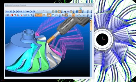
With CAM software. For most real parts the program comes from CAM software. The programmer imports a 3D model, chooses tools and toolpath strategies, and the software calculates the moves. A post-processor then writes them out as G-code for one specific machine.
Common Mistakes Beginners Make
- Mixing up absolute (G90) and incremental (G91) positioning, which sends the tool somewhere unexpected.
- Forgetting that a mode is still active from earlier lines, such as an uncancelled canned cycle that drills at every new position.
- Forgetting to set units, so a program written in millimetres runs in inches.
- Leaving out the decimal point. On many industrial controls X10 is read in the smallest unit, 0.010 mm, while X10. or X10.0 means 10 mm.
- Using rapid moves (G00) too close to the part or the clamps.
- Running a program without checking the work offset and tool length offsets.
- Skipping simulation and finding the collision on the machine instead of on the screen.
Do You Need to Learn G-Code?
If you operate or set up a CNC machine, yes. Reading a program lets you spot problems before pressing cycle start and make small edits at the control. If you only design parts, a working knowledge is enough: it shows you why some features are quick to machine and others are not.
G-Code FAQ
What does the G in G-code stand for?
The standard calls G-codes preparatory functions: they prepare the machine for the type of move that follows. M-codes are miscellaneous functions. The letter G itself is simply the address chosen for that group.
Is G-code a programming language?
Yes, but a simple one. Basic G-code is a list of instructions with no variables or loops. Many industrial controls add macro features, such as variables, conditions, and subprograms, on top of it.
What is the difference between G00 and G01?
G00 moves at the machine’s maximum speed and is only for moving through air. G01 moves in a straight line at the programmed feed rate and is used for cutting.
Is 3D printer G-code the same as CNC G-code?
They share the motion codes, but printers add codes for heating and extrusion, and some numbers mean different things. Printer files and CNC files are not interchangeable.
How can I practise G-code without a machine?
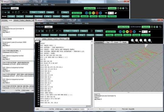
Use a G-code simulator or a free online G-code viewer. You paste the program and watch the toolpath drawn on screen, which shows most mistakes before any metal is cut.
Need G-Code You Can Trust on the Machine?
RunTechEngineer prepares machine-ready CNC programs, from toolpath programming and simulation to post-processing for your specific controller. Explore our CAM programming services or contact us to discuss your part.