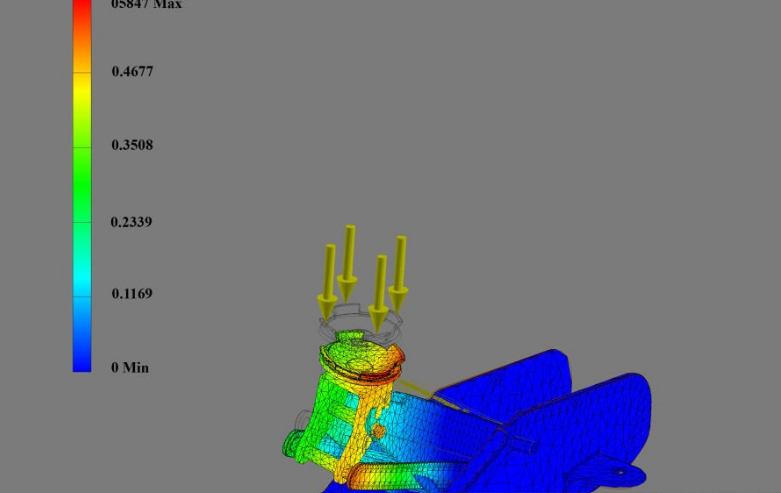
The factor of safety is how many times stronger a part is than it needs to be for the load it carries. A bracket with a factor of safety of 2 could take twice its working load before it yields. This guide gives the factor of safety formula, explains margin of safety, lists the values that design codes require, and shows how to pick a sensible number for your own part.
What Is a Factor of Safety?
A factor of safety (FoS), also called a safety factor and written as n or SF, compares the strength of a part with the stress or load it actually sees. Engineers use it because loads, material properties, and calculations are never known exactly. The factor covers that uncertainty.
The term is used in two related ways, and mixing them up causes confusion:
- Design factor (required factor of safety). The minimum value the design must reach. It is set by a code, a standard, a contract, or company practice before any calculation is done.
- Actual factor of safety. The value the finished design really achieves, calculated from its stresses and its material strength.
A design passes when its actual factor of safety is equal to or greater than the design factor. A shaft that achieves 2.6 against a required 2.0 passes. One that achieves 1.8 does not.
The Factor of Safety Formula
The basic factor of safety formula divides what the part can withstand by what it has to withstand:
Factor of safety = failure strength ÷ actual stress
Which strength you use depends on how the part would fail.
- Ductile metals (steel, aluminium, copper) are normally checked against yield, because permanent bending already means the part has failed: n = Sy ÷ σ, where Sy is the yield strength and σ is the working stress.
- Brittle materials (cast iron, glass, ceramics, many resins) break without yielding, so they are checked against ultimate tensile strength: n = Su ÷ σ.
- Whole components such as a bolt, a sling, or a purchased bearing are often rated by load rather than stress: n = failure load ÷ working load.
For a combined stress state, such as a shaft in bending and torsion, σ is the von Mises stress rather than a single direct stress.
The same idea can be turned around to size a part. Divide the strength by the design factor to get the allowable stress, then make the part big enough that the working stress stays below it:
Allowable stress = strength ÷ design factor
Factor of Safety vs Margin of Safety
Margin of safety is the spare capacity above the working load, so it is one less than the factor of safety:
Margin of safety = factor of safety − 1
A factor of safety of 1.8 is a margin of safety of 0.8, or 80% extra capacity. A margin of zero means the part is exactly at its limit, and a negative margin means it fails before reaching the working load.
Aerospace teams, including NASA, often use a second convention: they apply the required design factor first and then report the margin left over. Under that convention any margin of zero or more passes. When you read a stress report, check which convention it uses before comparing numbers.
Worked Example: An Aluminium Rod in Tension
A hanger rod made of 6061-T6 aluminium carries a steady tensile load of 15 kN. The rod is 12 mm in diameter. Is it safe, and what size would meet a design factor of 3?
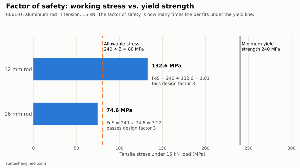
Step 1: the stress. The cross-section area is π × 6² = 113.1 mm². The tensile stress is 15,000 N ÷ 113.1 mm² = 132.6 MPa.
Step 2: the material strength. Typical 6061-T6 at room temperature has a yield strength of about 276 MPa and an ultimate strength of about 310 MPa. The minimum values guaranteed for extruded bar are lower: 240 MPa yield and 260 MPa ultimate. A design check should use the guaranteed minimums.
Step 3: the factor of safety.
| Check | Strength used | Factor of safety |
|---|---|---|
| Against yield, minimum strength | 240 MPa | 240 ÷ 132.6 = 1.81 |
| Against ultimate, minimum strength | 260 MPa | 260 ÷ 132.6 = 1.96 |
| Against yield, typical strength | 276 MPa | 276 ÷ 132.6 = 2.08 |
The same rod looks like it has “a factor of safety of about 2” or “1.8” depending only on which strength value you pick. The honest answer is 1.81 against yield, a margin of safety of 0.81.
Step 4: sizing for a design factor of 3. The allowable stress is 240 ÷ 3 = 80 MPa. The area needed is 15,000 ÷ 80 = 187.5 mm², which is a diameter of 15.5 mm. The next standard size is 16 mm. At 16 mm the stress is 74.6 MPa and the factor of safety against yield is 3.22.
This is a static check only. If the load cycles on and off, fatigue usually governs long before yield; see fatigue analysis.
Factor of Safety Values Required by Codes
Where a design code applies, it sets the factor for you. These are some widely used examples:
| Code or field | Required factor | Applied to |
|---|---|---|
| Transport aircraft (FAA, 14 CFR 25.303) | 1.5 | Limit load (the largest load expected in service) |
| Pressure vessels (ASME Section VIII, Division 1) | 3.5 on ultimate, 1.5 on yield | Material strength, whichever gives the lower allowable stress |
| Pressure vessels (ASME Section VIII, Division 2) | 2.4 on ultimate, 1.5 on yield | Material strength, lower of the two |
| Structural steel in tension (AISC, allowable strength design) | 1.67 for yielding, 2.00 for rupture | Nominal strength |
| Wire rope and synthetic slings (ASME B30.9 practice) | 5 | Breaking strength |
| Alloy steel chain slings (grade 100) | 4 | Breaking strength |
The AISC value of 1.67 is why older steel handbooks give an allowable tensile stress of 0.6 × yield: 1 ÷ 1.67 = 0.6.
Codes change and each one has its own conditions, so always work from the current edition of the code that applies to your product. For lifting gear, use the working load limit the manufacturer marks on the item.
How to Choose a Factor of Safety When No Code Applies
Many machine parts, fixtures, and brackets fall outside any code. A common general range is about 1.5 to 2 for well-understood ductile metal parts under steady load, around 3 for parts with uncertain loads such as vehicle components, and 4 or more where a failure could injure someone. Our FEA failure example shows these figures applied to a real bracket.
Rather than picking a number from a table, ask what is uncertain and what is at stake:
| Question | Lower factor is reasonable when… | Higher factor is needed when… |
|---|---|---|
| How well are the loads known? | Loads are measured or fixed by geometry | Loads are estimated, or shocks and misuse are likely |
| How well is the material known? | Certified metal with minimum strengths | Castings, welds, recycled stock, or 3D printed plastic |
| How good is the analysis? | Simple shape, checked by hand and by FEA | Complex geometry, rough estimate only |
| How does it fail? | Ductile, bends visibly before it breaks | Brittle, breaks without warning |
| What happens if it fails? | Replaceable part, no one nearby | Injury, large loss, or a long stoppage |
| Can it be tested? | A prototype will be load-tested | No test is possible before use |
Each answer in the right-hand column pushes the factor up. Weight-critical products such as aircraft and racing parts use low factors, but only because their loads, materials, and analysis are all tightly controlled and tested.
Plastics and 3D printed parts
Plastics need more caution than metals. Their strength drops with temperature, they creep under constant load, and 3D printed parts are much weaker across their layers than along them. For a functional printed part, use the strength across the layers, not the datasheet value for a moulded test bar, and allow a larger factor. Our guide to how strong PLA is gives real numbers, and 3D printing tolerances covers wall thickness.
Common Mistakes with Safety Factors
- Using typical strength instead of minimum strength. In the example above this alone moved the answer from 1.81 to 2.08.
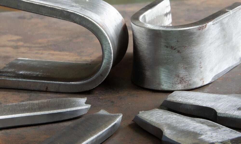
- Checking against ultimate when yield is the real limit. A ductile part that has permanently bent has usually failed already.
- Ignoring stress concentrations. Holes, keyways, and sharp corners raise local stress two or three times above the nominal value. The factor of safety must be calculated from the peak stress.
- Treating a static factor as a fatigue check. A part with a factor of 3 on yield can still crack under millions of load cycles. Fatigue needs its own check against the endurance or fatigue strength.
- Assuming a factor on load equals a factor on stress. That is true only when stress rises in direct proportion to load. Buckling, contact, and large deflections break this rule; a slender column can collapse suddenly well below the load a simple stress check predicts.
- Stacking factors. Adding a factor to the load, another to the material, and a third to the result multiplies them. Three factors of 1.5 make 3.4, which may be far more than intended.
- Making the factor too high. Every extra unit of safety factor adds weight and cost. A large factor is not a substitute for knowing the loads.
Factor of Safety FAQ
What is a good factor of safety?
If a code applies, the code’s value is the answer. Without one, about 1.5 to 2 suits well-understood ductile metal parts under steady load, around 3 suits parts with uncertain loads, and 4 or more suits parts whose failure could hurt someone.
Can a factor of safety be less than 1?
Yes, as a calculated result, and it means the part is expected to fail under the working load. A design factor is never set below 1.
What is the difference between factor of safety and margin of safety?
Margin of safety is factor of safety minus 1. A factor of safety of 2.5 is a margin of safety of 1.5, meaning 150% spare capacity beyond the working load.
Should I use yield strength or ultimate strength?
Use yield strength for ductile metals where permanent deformation counts as failure. Use ultimate strength for brittle materials, and where a code specifies it, as the ASME pressure vessel code does.
How do I get the factor of safety from FEA?
Divide the material’s yield strength by the peak von Mises stress in the area that matters, ignoring single-element spikes at sharp corners and load points. Many FEA programs plot this ratio directly as a safety factor map.
Not Sure Your Design Has Enough Margin?
RunTechEngineer checks parts by hand calculation and finite element analysis, reports the factor of safety against yield and fatigue, and shows where the design can be lightened or must be strengthened. Contact us with your model, material, and loads.