Finite element analysis (FEA) is a computer method for predicting how a part behaves under load, heat, or vibration before it is built. It works by dividing the part into thousands of small, simple pieces called elements, calculating how each one responds, and combining the results into a picture of the whole part.
Engineers use it to answer practical questions. Will this bracket bend? Where will this frame crack first? How hot will this housing get? This guide explains how FEA works, the main types of analysis, how to read the results, and what FEA cannot tell you.
Why Parts Are Divided into Elements
The equations that describe stress in a simple shape, such as a straight beam or a round shaft, can be solved by hand. Real parts are not simple. A machined bracket with holes, fillets, and ribs has no neat formula.
FEA gets around this by replacing one impossible problem with many easy ones. A complicated part is cut into small elements, usually tetrahedra or bricks, each simple enough to describe with basic equations. The elements are joined at shared points called nodes. The software writes the equations for every element, assembles them into one large system, and solves it.
The collection of elements is called the mesh. The underlying mathematics is the finite element method (FEM); FEA is the name for applying it to an engineering problem. In practice the two terms are used interchangeably.
How FEA Works, Step by Step
- Geometry. Start from the 3D CAD model. Small features that do not affect strength, such as logos and tiny chamfers, are usually removed to keep the model manageable.
- Material. Assign the properties the solver needs. For a basic stress study these are the elastic modulus, Poisson’s ratio, and density, plus the yield strength for judging the result.
- Mesh. Divide the part into elements. Smaller elements give more accurate results and longer solve times, so the mesh is made fine where stress changes quickly, around holes and corners, and coarser elsewhere.
- Supports. Define how the part is held: which faces are fixed, which can slide, and which are bolted.
- Loads. Apply the forces, pressures, torques, temperatures, or accelerations the part will see in use.
- Solve. The software calculates the displacement of every node, then derives strain and stress from those displacements.
- Review. Examine the results, check that they make physical sense, and refine the mesh to confirm the answer does not change.
Steps 4 and 5 decide whether the result means anything. The solver will happily calculate a precise answer to the wrong question. A part that is held or loaded differently in the model than in reality gives a result that looks convincing and is wrong.
Types of FEA
“Running an FEA” can mean several different studies. Each answers a different question.
| Analysis type | Question it answers | Typical use |
|---|---|---|
| Linear static | How much does it stress and deflect under a steady load? | Brackets, frames, housings |
| Modal | At what frequencies does it naturally vibrate? | Avoiding resonance in machines and drone frames |
| Buckling | At what load does a slender part suddenly collapse sideways? | Columns, thin panels, struts |
| Thermal | How does heat spread, and how much does the part expand? | Electronics housings, engine parts |
| Fatigue | How many load cycles before a crack starts? | Shafts, springs, anything loaded repeatedly |
| Nonlinear | What happens after yielding, with large movement, or with parts in contact? | Snap fits, rubber seals, forming, impact |
| Dynamic | How does it respond to a load that changes with time? | Shock, drop tests, rotating machinery |
Most everyday design work is linear static analysis, sometimes followed by a modal or fatigue study. Nonlinear and dynamic studies take more time and more expertise, so they are used when the simpler ones cannot describe the problem. For heat-related work see thermal simulation, and for repeated loading see our guide to fatigue failure.
How to Read FEA Results
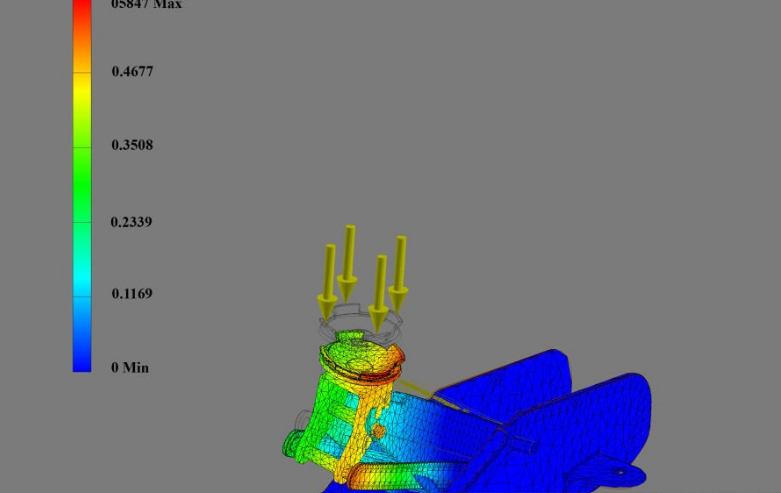
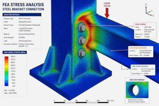
The familiar output is a colored plot, with blue for low values and red for high. Three plots matter most in a structural study.
- Stress shows where the material is working hardest. For metals the usual plot is von Mises stress, compared against the yield strength of the material.
- Displacement shows how far each point moves. A part can be strong enough and still deflect too much to do its job.
- Safety factor shows the material’s strength divided by the calculated stress at each point. Values below 1 mean the part is predicted to yield there.
Two cautions apply. First, red only means “highest in this plot”, not “dangerous”. Always read the numbers on the scale. Second, the deformed shape on screen is usually exaggerated many times so you can see it, and the real movement may be a fraction of a millimeter.
A worked case with numbers, including a hand calculation to check the software, is in our guide to predicting mechanical failure with FEA. See our full guide to von Mises stress.
Where FEA Is Used
- Machine design: checking frames, brackets, and shafts for strength and stiffness before fabrication.
- Weight reduction: finding material that carries little load and can be removed, which is the basis of design optimization.
- Aerospace and drones: confirming that light structures such as drone airframes survive flight and landing loads.
- Automotive: suspension parts, crash structures, and engine components.
- Consumer products: snap fits, enclosures, and drop performance.
- Failure investigation: reproducing the conditions under which a part broke, to find out why.
In everyday engineering use, FEA means the analysis of solid parts. When the problem is about air or liquid flow, the tool is CFD; we explain the difference in FEA vs CFD.
What FEA Cannot Do
FEA is a calculation, not a test. Its limits are worth knowing before you rely on a result.
- It only knows what you tell it. Loads you did not model, defects in the material, poor welds, and corrosion are not in the answer.
- The result is only as good as the inputs. Most errors come from wrong supports, wrong loads, or wrong material data, not from the software.
- A coarse mesh gives a wrong number with full confidence. Results should be checked by refining the mesh until they stop changing.
- Sharp corners produce false peaks. A perfectly sharp internal corner reports a stress that keeps rising as the mesh gets finer. Real parts have a radius, and the model should too.
- A basic study assumes the material stays elastic. Once the predicted stress passes yield, a linear analysis no longer describes what happens.
- It does not replace testing for critical parts. Where failure would be dangerous or expensive, simulation narrows the design and a physical test confirms it.
FEA Software
FEA is available at every budget. Dedicated packages such as Ansys, Abaqus, and Nastran-based solvers are used for demanding work. CAD systems including SolidWorks, Autodesk Fusion, and Inventor have built-in simulation that covers most everyday static, modal, and thermal studies. FreeCAD, with the CalculiX solver, is a free open-source option.
The software matters less than the person setting up the model. A simple tool used with correct loads and supports beats an advanced one used carelessly.
Frequently Asked Questions
What is finite element analysis in simple terms?
It is a way of testing a design on a computer. The part is split into many small pieces, the computer calculates how each piece responds to the applied loads, and the results show where the part is stressed, how much it deforms, and whether it is likely to fail.
What is the difference between FEA and FEM?
FEM, the finite element method, is the mathematical technique. FEA, finite element analysis, is the use of that technique to study a real engineering problem. Most people use the two terms to mean the same thing.
What is FEA used for?
Checking strength and stiffness, finding weak points, predicting vibration and heat behavior, estimating fatigue life, and reducing weight, all before a physical part is made.
Is FEA accurate?
Yes, when the model matches reality. For a well-built model of a metal part under known loads, results close to physical test are realistic. Accuracy drops quickly when the supports, loads, or material properties are guessed.
Do I need FEA for every part?
No. Simple shapes under simple loads can be checked with hand calculations, and low-risk parts may not need analysis at all. FEA earns its cost on complex geometry, on parts where failure matters, and where saving weight or material is worth the effort.
How long does an FEA take?
A linear static study of a single part often solves in minutes. Most of the time goes into preparing the model and checking the result, not into the calculation. Nonlinear and dynamic studies of assemblies can take hours or days.
Need Confidence in a Design Before Building It?
RunTechEngineer provides FEA services for parts and assemblies: stress, deflection, vibration, thermal, and fatigue studies, each checked against hand calculations. See our full mechanical simulation services, or contact us with your model and how the part will be loaded.