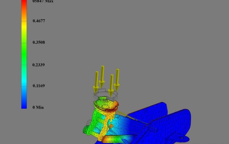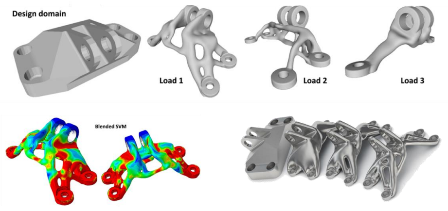
Topology optimization is a simulation method that decides where material should go inside a part. You give it a block of space, the loads, the supports, and a target such as “use 40% of the material”, and it removes everything that is not carrying load. The result is often a light, organic shape that a designer would not have drawn by hand. This guide explains how topology optimization works, walks through a typical workflow, and covers the limits to watch for.
What Is Topology Optimization?
Topology optimization finds the best layout of material within a given design space for a given set of loads, supports, and constraints. Unlike most design changes, it does not start from an existing shape and adjust it. It is free to put material anywhere in the space, add holes, join members, or remove whole regions.
It is one of three kinds of structural optimization:
| Type | What it changes | Example |
| Size optimization | Dimensions of an existing design | The wall thickness of a tube, the flange width of a beam |
| Shape optimization | The outline of existing features | The radius of a fillet, the curve of a boundary |
| Topology optimization | Where material exists at all, including the number of holes and members | Turning a solid plate into a frame of struts |
Because it can change the layout itself, topology optimization is used at the concept stage, before the detailed design is fixed. Size and shape optimization are then used to fine-tune the result.
How Topology Optimization Works
Most commercial tools use a density method called SIMP (Solid Isotropic Material with Penalization). The idea is simple even if the maths is not.
- Divide the design space into elements. The space is meshed just as it would be for finite element analysis.
- Give every element a density between 0 and 1. A density of 1 means solid material; 0 means empty. The optimizer usually starts with every element at the target fraction, for example 0.4.
- Link stiffness to density with a penalty. An element’s stiffness is its density raised to a power, typically 3. At a density of 0.5 the element has only 0.5³ = 12.5% of full stiffness but still “costs” 50% of the material. That makes half-dense material a poor bargain, so the optimizer pushes each element towards 0 or 1.
- Solve the FEA model and work out the sensitivity. For every element, the solver calculates how much the whole part’s stiffness would improve if that element had a little more material.
- Move material to where it helps most. Density is added where the sensitivity is high and removed where it is low, while the total amount of material stays at the target.
- Repeat until the layout stops changing. A typical run takes from tens to a few hundred iterations.
The most common goal is to minimize compliance, which means making the part as stiff as possible for a fixed amount of material. Other goals include minimizing mass while keeping stress or deflection below a limit, or raising a natural frequency.
Two numerical problems must be controlled. Without a filter, the solution forms a checkerboard of solid and empty elements that looks stiff to the solver but is not real. The result can also depend on the mesh, with finer meshes giving ever finer details. A filter radius, or a minimum member size, keeps the members thick enough to make sense.
A Worked Example: A Cantilever Bracket
The image below is a real topology optimization run. The design space is a rectangle twice as long as it is high, fixed along its left edge and loaded downward at the middle of its right edge. The target was 40% of the material.
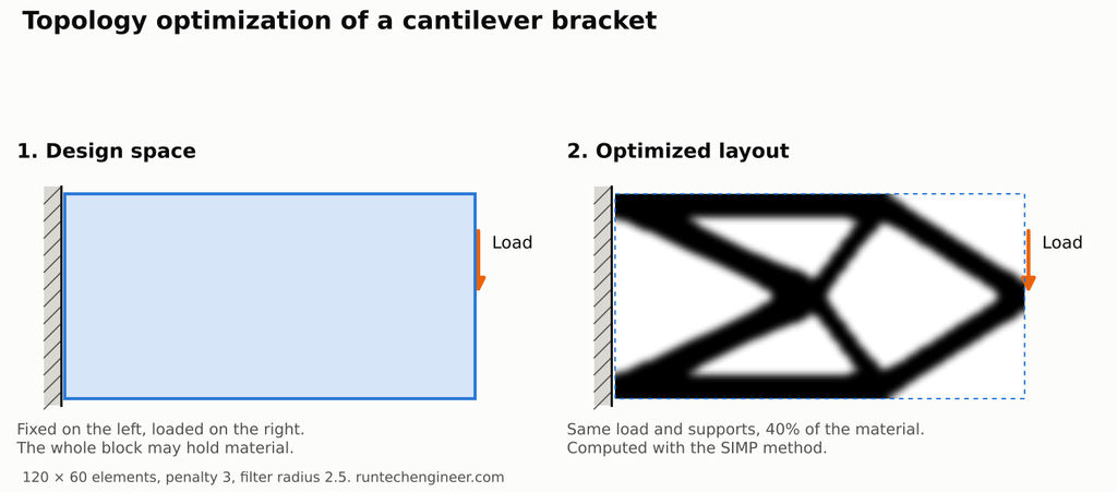
The optimizer turned the solid block into a truss: two outer chords that carry the bending as tension on top and compression underneath, joined by diagonals that carry the shear. That is the same layout an experienced engineer would choose for a lightweight bracket, found here without any human input beyond the loads, supports, and target.
The run used a mesh of 120 × 60 elements, a penalty power of 3, and a filter radius of 2.5 elements, following the classic educational codes from the Technical University of Denmark: Ole Sigmund’s 99-line MATLAB code and its faster 88-line successor.
A Topology Optimization Workflow, Step by Step
- Define the design space. Model the largest volume the part may occupy. Leave out clearance zones for bolts, shafts, cables, and neighbouring parts.
- Mark the non-design regions. Bolt bosses, bearing seats, and mounting faces must stay solid. Mark them so the optimizer cannot remove them.
- Apply every load case. A bracket that sees a vertical load in service and a sideways knock during assembly needs both cases. An optimizer only strengthens the part against the loads it is given, and will happily remove material that an unmodelled load needed.
- Set supports realistically. A support that is stiffer than reality moves load paths and gives a misleading shape.
- Choose the goal and the limit. Typical choices are “stiffest part at 30% of the material” or “lightest part that keeps deflection under 0.5 mm”.
- Add manufacturing constraints. Minimum member size, symmetry, a draw direction for casting or moulding, or an extrusion direction for a constant cross-section all change the result. Set them before you run, not after.
- Run and read the result. The output is a density field or a rough mesh, not a finished part. Look for the load paths and the overall layout rather than the exact edges.
- Rebuild the geometry. Redraw the shape as clean CAD, smoothing members, adding fillets, and sizing holes. A mesh straight from the optimizer is rarely fit to send to a machine shop; see STL vs STEP for why.
- Verify with a normal FEA. Run a stress analysis on the rebuilt part. Check the peak von Mises stress, the deflection, and the factor of safety. If the part carries a cycling load, check fatigue as well; topology optimization for stiffness does not check either.
Making Optimized Parts: 3D Printing, Casting, and CNC
The organic shapes that topology optimization produces are hard to machine but well suited to additive manufacturing. A 3D printer builds a branching truss as easily as a solid block.
A well-known example is GE’s 2013 jet engine bracket challenge. Nearly 700 designs were entered from 56 countries. The winner, M Arie Kurniawan, an engineer from Salatiga in Central Java, Indonesia, cut the bracket’s weight from 2,033 g to 327 g, a reduction of almost 84%. The printed titanium part then survived GE’s load testing.
Each process needs different constraints:
| Process | What to set in the optimization | What to check afterwards |
| Metal 3D printing | Minimum member size; overhang control if the tool has it | Support removal, residual stress, powder escape |
| Plastic 3D printing | Minimum member size above about two nozzle widths | Layer direction; printed plastic is weaker across its layers. See functional 3D printed parts |
| Casting and moulding | Draw direction, so no undercuts form | Draft angles, even wall thickness |
| CNC machining | Extrusion or draw direction from the tool axis; larger minimum member size | Tool access, internal corner radii. See design for manufacturing |
For machined parts, the most practical use is often as a guide. Let the optimizer show where the load runs, then design simple pockets and ribs that follow those paths.
Topology Optimization vs Generative Design
The two terms are often used as if they meant the same thing. Autodesk, which sells generative design tools, draws the line like this:
- Topology optimization starts from a design space you have already modelled and returns one optimized concept, usually as a mesh that must be rebuilt in CAD.
- Generative design starts from the regions to keep, the regions to avoid, the loads, and the manufacturing methods, and returns many alternative designs, often as editable CAD with cost estimates.
In practice, generative design tools run topology optimization, or similar methods, many times with different settings and processes. For a single part with known loads, plain topology optimization is usually enough.
Topology Optimization Software
Topology optimization is built into most major simulation and CAD packages, including Altair OptiStruct and Inspire, Ansys Mechanical, Abaqus (Tosca), Siemens NX and Simcenter, SolidWorks Simulation, and Autodesk Fusion. They differ in the goals, load types, and manufacturing constraints they support. For learning, the free educational codes from the Technical University of Denmark show the whole method in under a hundred lines.
Common Mistakes
- Missing load cases. The optimizer removes material that only an unmodelled load needed. This is the most common cause of a failed optimized part.
- Too small a design space. If the space is barely bigger than the original part, there is little left to optimize.
- Treating the output as the final part. The raw result has jagged edges and thin, uncertain members. It must be rebuilt and checked.
- Optimizing for stiffness only. A stiffness-optimized part can still have local stress peaks, buckle, or crack in fatigue. Each needs its own check.
- Forgetting how it will be made. A beautiful organic bracket that no one can machine or afford to print is not an improvement.
Topology Optimization FAQ
What is topology optimization used for?
It is used to make parts lighter while keeping them stiff and strong, mainly in aerospace, automotive, robotics, medical implants, and any part that will be 3D printed. It is most useful at the concept stage, before the shape is fixed.
How much weight can topology optimization save?
It depends on how much extra material the original design carried. A part that was designed with generous, uniform walls has more to lose than one that was already carefully sized. Very large savings, like the 84% in GE’s bracket challenge, come from rethinking a part entirely for 3D printing.
Is topology optimization the same as generative design?
Not quite. Topology optimization returns one optimized layout from a design space you define. Generative design explores many options with different processes and settings, and often uses topology optimization inside.
Can I use topology optimization for CNC machined parts?
Yes, with an extrusion or draw-direction constraint so the result has no undercuts the tool cannot reach. Many engineers use the result as a guide for placing pockets and ribs rather than machining the organic shape directly.
Does topology optimization replace FEA?
No. It uses FEA inside every iteration, and the rebuilt part still needs a normal stress, deflection, and fatigue analysis before it is released.
Want a Lighter Part That Still Does Its Job?
RunTechEngineer uses topology optimization and design optimization to remove weight and material from brackets, frames, and housings, then checks the result with finite element analysis before it is made. Contact us with your part, its loads, and how you plan to make it.